I have explained how to make an automatic water level controller using Arduino and float sensors in this simple Arduino project.

This water level monitoring system will also check the water level in both the overhead and underground water tank and accordingly control the water pump automatically.
You can always monitor the tank water level for both the water tank and manually control the water pump in manual mode.
Following all the steps, you can easily make this automatic water level monitoring system using Arduino and float sensors.
Table of Contents
Required Components for Water Level Controller

- Arduino UNO or Arduino Nano
- Float switch sensor 2no
- 30A 5V SPDT relay module
- 1k 0.25watt Resistors – 8 no (R1 – R8)
- 10k 0.25watt Resistors – 4 no (R9 – R12)
- BC547 NPN Transistor (Q1)
- LED 5mm – 7no
- 2-pin Terminal connectors (5 no)
- 3-pin Terminal connectors (3 no)
- 5V DC Buzzer
- Switches – 2no
- AC to DC converter 5V HLK-10M05 (Optional)
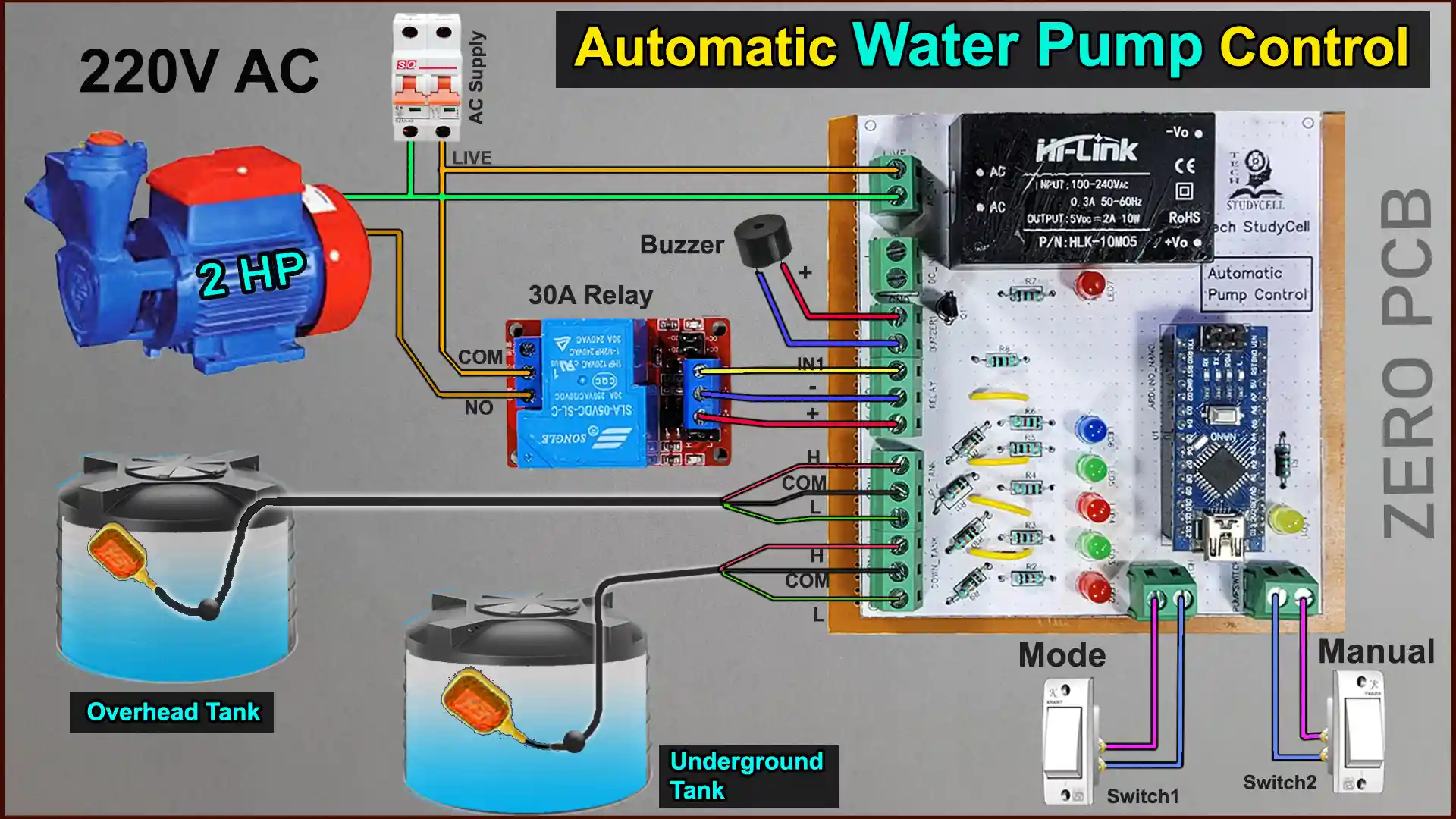
Circuit of Arduino-Based Water Level Controller
In the circuit, if you want to use AC voltage, then you have to use an HLK-10M05 AC to DC converter. Otherwise, you can directly give the 5V DC supply to this circuit.
The float switch for the overhead tank is connected with digital pins D9 & D10 of Arduino. And the D11 & D12 are connected to the underground tank float sensor switch.
The D8 & D7 are connected with the Mode switch and Pump ON/OFF switch.
The control pin of the 30A relay connected with the D5 pin of the Arduino Nano.
And the indicator LEDs and Buzzer are connected with digital pins D6, D13 & D4 of the Arduino.
PCB Layout for Water Level Sensor


Please download the PCB layout, then print it on the A4 page.
Please check the PCB size while printing, it should be the same as mentioned in Layout.

As shown in the video, with the help of the PCB Layout you can easily make the complete circuit on zero PCB.
Tutorial video on Arduino Water Level Controller
During the Arduino project video, I covered the following topics:
- Quick demo on Arduino-based water level controller works.
- Explained the circuit diagram of the Arduino water level sensor.
- How to make water level indicator on Zero PCB.
- Explained the source code for the Arduino project.
- Connection diagram for Water Pump & Float sensor
- Testing the Arduino-based water level controller circuit.
- How to install the water pump controller and float switch.
PCB for the Water Level Monitoring System

You can also download the PCB Gerber file and order the PCB from PCBWay.
About PCBWay and their services
You can order any custom design PCBs from PCBWay at very reasonable prices.

PCBWay not only produces FR-4 and Aluminum boards but also advanced PCBs like Rogers, HDI, and Flexible and Rigid-Flex boards, at very affordable prices.
For the online instant quote page please visit – pcbway.com/orderonline
You can also explore different PCB projects from their Open-source community pcbway.com/project/.
Source Codes for the Arduino-based Water Level Indicator
Click on the following buttons to download the source codes for this Arduino project.
If you refer to the same circuit, then no need to change anything in the code. You can directly upload it to Arduino Nano or Arduino UNO.
Installing the water pump controller and float switch

Now connect the float sensors, Relay, Pump, 5V Buzzer, and Switches as per the above diagram.
Here I have used a 30A relay (Active LOW), you can use the relay module as per the pump rating.

Please take proper safety precautions while connecting the AC voltage.
Testing the Water Pump Controller circuit

Before connecting the water pump, I will recommend testing the circuit by connecting an AC blub instead of the pump.
While testing, keep changing the float sensor switches position manually and observe the indicator LEDs and relay status.
If everything works fine, install the float switches in both the tank and connect the pump with the relay as per the circuit.
Installing the Float Sensor Switches

Each float switch has a counterweight, which can be adjusted.
First, define the Minimum and Maximum water level inside the tank.
Then place the counterweight in the middle of the Minimum and Maximum water level height. (As shown in the picture).

After placing the counterweight correctly, the float switch position will be as per the above picture for the empty and full water tank.

If required, you can connect extra wires with the float switch to cover the distance between the water tank and PCB.
I hope you like this simple Arduino project on the water level monitoring system using the float sensor switch and alarm.
Click Here for more such Arduino projects.
Please do share your feedback on this Arduino project. Thank you for your time.


