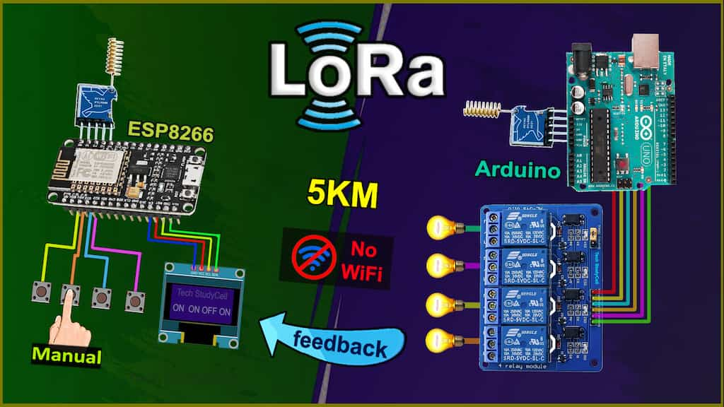
In this Lora project, I have shown how to make the LoRa Project using Arduino ESP8266 control relays with real-time feedback on an OLED display. Here I have used the RYLR896 LoRa module. Explained both the transmitter and receiving LoRa circuit and source codes and basic AT commands to configure the LoRa modules.

So if you follow all the steps, you can easily make this Lora Arduino project and control any appliances from 5KM away without Wi-Fi and Bluetooth. So this project is very useful in rural areas.
Table of Contents
Required Components for the LoRA Project

Transmitter Lora ESP8266 circuit:
- Lora Module REYAX RYLR998 1no
- ESP8266 NodeMCU 1no
- 1k Resistors 2no
- 4.7k Resistor 1no
- 10k Resistor 1no
- 5-mm LED 2no
- 0.96″ OLED Display
- Push-buttons 5no

Receiver Lora Arduino circuit:
- Lora Module REYAX RYLR998 1no
- Arduino UNO 1no
- 5v 4-channel Relay Module 1no
- 1k Resistor 1no
- 2k Resistor 1no
- 4.7k Resistor 1no
- 5-mm LED 1no
- Push-Buttons or Switch 4no
Transmitter Lora circuit using ESP8266

In the transmitter LoRa circuit, I have used ESP8266 NodeMCU. Here I have made a voltage divider using 4.7k and 10k resistors to drop down the 5V logic level to the 3.3V logic level for the serial communication with the LoRa module.
For the serial communication with the LoRa module, I have used D7 as RX and D8 as TX with the SoftwareSerial library.
The pushbuttons are connected with the SD3, D3, D5, RX, and D6 GPIO pins of the NodeMCU. ( Here SD3, D3, D5, RX are for controlling the relays, and D6 is used for requesting feedback from receiving side).
And the status LED is connected with the D4 pin.
You can use any 5V DC supply or 9V battery to supply the circuit.
Receiver Lora circuit using Arduino UNO

In the receiver LoRa circuit, I have used Arduino UNO. Also here I have made a voltage divider using 2k and 4.7k resistors to drop down the 5V logic level to the 3.3V logic level.
For the serial communication with the Lora module, I have used D2 as RX and D3 as TX with the SoftwareSerial library.
I have used D4, D5, D6 & D7 digital pins to control the 4-channel relay module.
And the GPIO D10, D11, D12 & D13 are connected with switches to control the relay module manually.
The LED is connected with the A3 pin.
As per the source code, when the control pins of the relay module receive the LOW signal the respective relay will turn on and the relay will turn off for the HIGH signal in the control pin.
I have used the INPUT_PULLUP function in Arduino IDE instead of using the pull-up resistors with each switch.
I have used a 5V 2Amp power supply to supply the Arduino UNO and relay module.
Please take the proper safety precautions while working with high voltage.
Tutorial video on Arduino ESP8266 LoRa Project
In the tutorial video, I have covered the following topics in detail.
- Demonstrated this ESP8266 Arduino Lora project.
- Explained Transmitter & Receiver Lora circuit.
- Configure LoRa with AT commands.
- Explained the source codes for this LoRA project.
- Control high voltage appliances with LoRa.
Important points of this Lora Project:
- The Network ID and BAND should be the same for the transmitter and receiving end Lora module.
- Set the BAND as per the eligible LoRa bands in your country.
- You can use any other microcontroller for this Lora project.
- All the AT commands for configuring the LoRa module are written in the void setup() function of the source code.
- The range for this LoRa project will be up to 5KM in rural areas. (Range will decrease if the number of obstacles increases in the signal path).
- After the restart, you have to wait till the STATUS LED turns OFF.
- Please watch the complete video, otherwise, you may face some issues.
Codes for this LoRa project using ESP8266 & Arduino
Click on the following buttons to download the source codes for this LoRa project.
Here, I have used the SoftwareSerial library for the serial communication with the LoRa module. So do not disconnect the LoRa module from the microcontroller while uploading the code and during the booting process.
AT commands used to configure the Lora modules
For this Lora project, you don’t have to separately configure the Lora modules. All the required AT commands are written in the void setup() function, which will execute after the booting process of the microcontroller.
For the Transmitter LoRa module
- AT+ADDRESS=1
- AT+NETWORKID=5
- AT+BAND=865000000
For the Receiver LoRa module
- AT+ADDRESS=2
- AT+NETWORKID=5
- AT+BAND=865000000
Here I have used the 865MHz band. Please enter the BAND as per the eligible LoRa band in your country.

After programming the NodeMCU and Arduino UNO, connect the 5V supply. then wait till the both Status LEDs turn OFF.
It may take few seconds as during this time NodeMCU or Arduino is configuring the LoRa module with AT commands.
PCB for the ESP8266 Transmitter LoRa circuit
Although the PCB is not mandatory, but if you want, you can also use this PCB to make the circuit compact and give the project a professional look.
Required Components for the PCB
- REYAX RYLR998 or RYLR896 1no
- ESP8266 NodeMCU 1no
- 1k Resistors 2no
- 4.7k Resistor 1no
- 10k Resistor 2no
- 5-mm LED 2no
- Push button 6no
- Jumper 2no
- Terminal connector 2 pin 1no
- OLED Display
Control the appliances with LoRa
Now, when you press the pushbutton in the transmitter circuit, the related relay should turn ON.
And after receiving the feedback from the receiver Lora circuit you can monitor the real-time status on OLED display.
Please watch the complete tutorial video for all the details.
Control Relays from Manual Switch

You can also control the appliances from manual switches or pushbuttons.
I hope you like this Lora projects idea with the Arduino ESP8266.
Click Here for more such ESP8266 projects.
Please do share your feedback on this IoT project. Thank you for your time.


