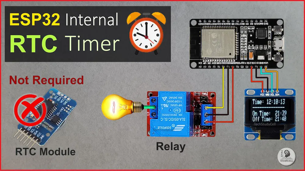
In this ESP32 project, I have shown how to make an ESP32 internal RTC timer control relay without any external RTC module.

The ESP32 will get the time from the NTP server initially, then it will use the internal RTC to calculate the time and accordingly control the relay.

Table of Contents
What is ESP32 internal RTC?
The ESP32’s internal RTC (Real-Time Clock) is a built-in feature that helps the device keep track of time even when it’s not connected to the internet or powered off. It’s like a tiny clock inside the ESP32 that runs independently.
Here’s how it works:
- Keeping time: The RTC keeps track of the current time, including hours, minutes, seconds, and even the date.
- Low power: It operates even when the main processor of the ESP32 is in sleep mode or powered off, consuming very little power.
- Accuracy: The RTC is relatively accurate and can maintain time over long periods, but it may need occasional adjustments to stay precise.
- Usage: Developers can utilize the internal RTC for various purposes like scheduling tasks, timestamping events, or triggering actions at specific times.
In summary, the ESP32’s internal RTC is like a mini clock that ensures your device knows what time it is, even when it’s not actively running.

In this article, I explained all the steps to make this ESP32 RTC home automation system, and how to fetch data from the NTP server.
In this ESP32 project, you can control the relay using ESP32 internal RTC, so you don’t need a Wi-Fi connection all the time.
Required Components for ESP32 Project:

Circuit of the ESP32 RTC Timer Relay

The circuit is straightforward, I have used D33 GPIO to control the relay module.
The OLED is optional. It is connected with D22 & D21 GPIO.
You can also use a 5V 5Amp mobile charger to supply the circuit instead of AC to DC converter.
For manual control, you can also connect a 5A latched switch across the COM & NO terminal of the relay as per the following circuit.

Please take proper safety precautions while connecting the AC appliances.
Tutorial video on ESP32 Internal RTC Project
In the ESP32 RTC tutorial video, I covered the following topics.
- Explained the circuit of the ESP32 RTC control relay.
- Explained the source code for the ESP32 internal Real Time Clock
- How to get the NTP server for your country.
- Control the relay using the ESP32 internal RTC Timer.
Although here I have not used any PCB, but I will always recommend to use a PCB for any electronics projects.
Now you can easily order your own custom-designed PCB from PCBWay at very reasonable prices.

PCBWay not only produces FR-4 and Aluminum boards but also advanced PCBs like Rogers, HDI, and Flexible and Rigid-Flex boards, at very affordable prices.
For the online instant quote page please visit – pcbway.com/orderonline
You can also explore different PCB projects from their Open-source community pcbway.com/project/.
For more details please visit the following articles.
Why PCBway
Get the NTP Server for your country
First, you have to find out the NTP server for your country.
Steps to get the NTP Server for your country
Visit www.ntppool.org

Select your country

You will get the server address on the top. Save it.
Program ESP32 with Arduino IDE
In the Tutorial video, I have explained all the steps to program the ESP32 using Arduino IDE.
- Update the Preferences –> Additional boards Manager URLs: https://dl.espressif.com/dl/package_esp32_index.json, http://arduino.esp8266.com/stable/package_esp8266com_index.json
- Then install the ESP32 board from the Board Manager or Click Here to download the ESP32 board.
- Download the required libraries as mentioned in the code:
- NTPClient
- Adafruit_GFX
- Adafruit_SSD1306
Code for the ESP32 Relay module
#include <WiFi.h>
#include <NTPClient.h>
#include <WiFiUdp.h>
#include <Wire.h>
#include <Adafruit_GFX.h>
#include <Adafruit_SSD1306.h>

// Replace these with your WiFi credentials
const char* ssid = "";  //mention WiFi name
const char* password = "";  //mention WiFi password

// Define NTP Server address
const char* ntpServer = "in.pool.ntp.org";  //Modify as per your country
const long  gmtOffset_sec = 19800; // Offset from UTC (in seconds) (India GMT 5:30 // 5.5*60*60 = 19800) Modify as per your country
const int   daylightOffset_sec = 3600; // Daylight offset (in seconds)

// Define relay pin
const int relayPin = 33; // Change this to the pin connected to your relay

// Define OLED parameters
#define SCREEN_WIDTH 128
#define SCREEN_HEIGHT 32
#define OLED_RESET    -1
Adafruit_SSD1306 display(SCREEN_WIDTH, SCREEN_HEIGHT, &Wire, OLED_RESET);

// Define NTP and WiFi objects
WiFiUDP ntpUDP;
NTPClient timeClient(ntpUDP, ntpServer, gmtOffset_sec, daylightOffset_sec);

// Define variables for relay control
const int relayOnHour = 21;   // Relay ON time in 24HR
const int relayOnMinute = 39; // Relay ON time Minute
const int relayOffHour = 21;   // Relay OFF time in 24HR
const int relayOffMinute = 40; // Relay OFF time Minute
bool relayState = false;

void setup() {
  Serial.begin(115200);

  // Initialize OLED display
  if(!display.begin(SSD1306_SWITCHCAPVCC, 0x3C)) {
    Serial.println(F("SSD1306 allocation failed"));
    for(;;);
  }
  display.clearDisplay();
  display.setTextColor(SSD1306_WHITE);
  display.setTextSize(1);
  display.setCursor(0, 0);
  display.println("Initializing...");
  display.display();
  delay(1000);

  // Connect to WiFi
  WiFi.begin(ssid, password);
  while (WiFi.status() != WL_CONNECTED) {
    delay(1000);
    Serial.println("Connecting to WiFi...");
  }
  Serial.println("Connected to WiFi");

  // Initialize relay pin as an output
  pinMode(relayPin, OUTPUT);
  //digitalWrite(relayPin, HIGH);  //uncomment for Active LOW relay
  digitalWrite(relayPin, LOW);   //comment for Active LOW relay

  // Start NTP time sync
  timeClient.begin();
  timeClient.update();
}

void loop() {
  // Update NTP time
  timeClient.update();

  // Get current time
  time_t currentTime = timeClient.getEpochTime();
  struct tm * timeinfo;
  timeinfo = localtime(¤tTime);

  // Display current time on OLED
  display.clearDisplay();
  display.setCursor(0, 0);
  display.print("Time: ");
  display.println(timeClient.getFormattedTime());
  display.println("--------------");
  display.print("On Time:  ");
  display.print(relayOnHour);
  display.print(":");
  display.println(relayOnMinute);
  display.print("Off Time: ");
  display.print(relayOffHour);
  display.print(":");
  display.println(relayOffMinute);
  display.display();

  // Check if it's time to toggle the relay
  if (timeinfo->tm_hour == relayOnHour && timeinfo->tm_min == relayOnMinute) {
    // Turn on the relay
    //digitalWrite(relayPin, LOW); //uncomment for Active LOW relay
    digitalWrite(relayPin, HIGH);  // comment for Active LOW relay
    relayState = true;
    Serial.println("Relay ON");
  }
  else if (timeinfo->tm_hour == relayOffHour && timeinfo->tm_min == relayOffMinute){
    // Turn off the relay
    //digitalWrite(relayPin, HIGH);  //uncomment for Active LOW relay
    digitalWrite(relayPin, LOW);  // comment for Active LOW relay
    relayState = false;
    Serial.println("Relay OFF");
  }
  // Wait for 1 second before checking again
  delay(1000);

}
In the code update the following details.
Enter the Wi-Fi name and Wi-Fi password in the code.
// Replace these with your WiFi credentials
const char* ssid = "";  //mention WiFi name
const char* password = "";  //mention WiFi password
Define the NTP Server address. You have to update the NTP server according to your country.
// Define NTP Server address
const char* ntpServer = "in.pool.ntp.org";  //Modify as per your country
const long  gmtOffset_sec = 19800; // Offset from UTC (in seconds)
const int   daylightOffset_sec = 3600; // Daylight offset (in seconds)
Mention the ON/OFF time for the Relay in 24H format (as shown).
// Define variables for relay control
const int relayOnHour = 21;   // Relay ON time in 24HR
const int relayOnMinute = 39; // Relay ON time Minute
const int relayOffHour = 21;   // Relay OFF time in 24HR
const int relayOffMinute = 40; // Relay OFF time Minute
Now upload the code to ESP32.
The ESP32 will get the time from the NTP server initially, then it uses the internal RTC to control the relay.
Now ESP32 RTC will control the Relay

Now the ESP32 will control the relay as per the predefined time mentioned in the source code.
I hope you like this Smart house IoT project idea with the Espressif ESP32.
Click Here for more such ESP32 projects.
Please do share your feedback on this IoT project. Thank you for your time.


