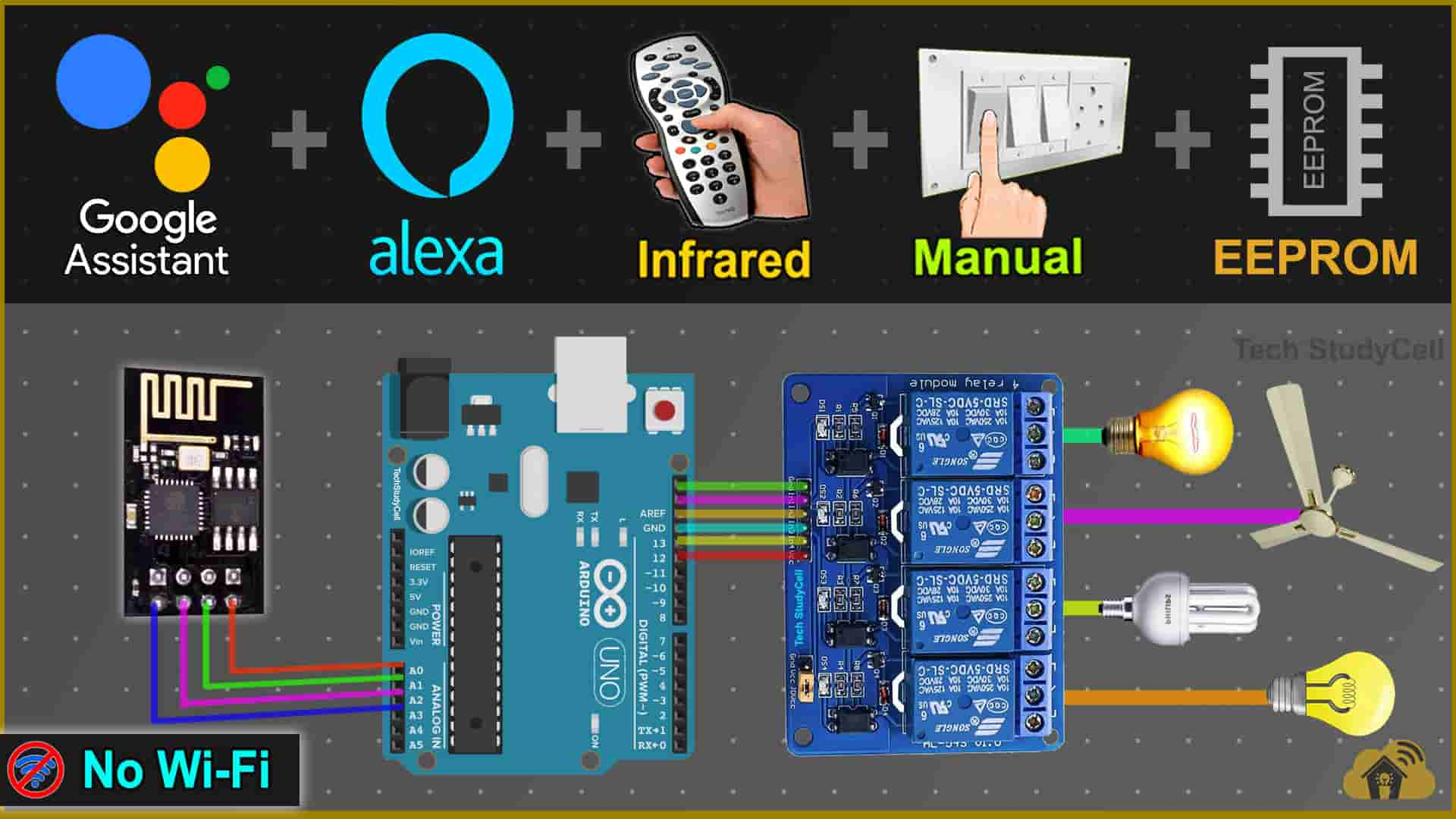
In this Arduino IoT project, I have explained how to make IoT-based home automation using Arduino UNO and ESP8266 ESP-01 to control relays with Google Assistant, Alexa, IR remote, and manual switches. You can also control the appliances and monitor real-time feedback in the Google Home and Amazon Alexa App from anywhere in the world.
You can also control the relays from the IR remote and manual switches if there is no internet available.
Here Arduino saves the previous state in EEPROM, so after power cuts when the power comes back appliances will automatically turn on according to the previous state.

For this project, I have used all the FREE tools. So if you follow all steps, you can easily make this Smart Home System with Google Home and Amazon Alexa to control the appliances with voice commands.
And you don’t need any Google Nest or Amazon Echo Dot devices for this voice control home automation project.
Table of Contents
Required Components for Arduino projects
- Arduino UNO or Arduino Nano
- ESP8266 ESP-01
- 1838 IR receiver (with metal case)
- 1k, 2k, 4.7k resistors (1/4 watt)
- 5-mm LED
- 1117 3.3V voltage regulator
- 4-channel 5V SPDT Relay Module
- Switches or Push Buttons
- FTDI232 USB to TTL
- 5V DC supply
Circuit of the Arduino IoT Project using ESP-01

The circuit is very simple, I have used D4, D5, D6 & D7 GPIO to control the 4-channel relay module.
And the GPIO D10, D11, D12 & D13 are connected with switches to control the relay module manually.
The output pin of the IR receiver is connected with A0.
For the serial communication with the ESP-01, I have used D2 as RX and D3 as TX with the SoftwareSerial library.
Here I have made a voltage divider using 2k and 4.7k resistors to drop down the 5V logic level to the 3.3V logic level for the serial communication with the ESP-01 WiFi module.
I have used the INPUT_PULLUP function in Arduino IDE instead of using the pull-up resistors with each switch.
As per the source code, when the control pins of the relay module receive the LOW signal the relay will turn on and the relay will turn off for the HIGH signal in the control pin.
I have used an 1117 3.3V voltage regulator to supply the ESP01. If you use Arduino UNO then you can use the 3.3V pin instead of the 1117 3.3V regulator but for Arduino Nano, you have to use the 1117 3.3V voltage regulator.

If you want to use push-button for manual control, then just connect pushbuttons instead of latched switches.
Please take the proper safety precautions while working with high voltage.
I have used a 5V 2Amp DC power supply for the circuit.
Tutorial video on Arduino IoT Project with ESP01
In the tutorial video, I have covered the following topics in detail.
- Demonstrated how the Arduino IoT project works.
- Explained circuit of Arduino ESP8266 control relay.
- Setup Sinric Pro account for ESP8266.
- Program the ESP-01 and Arduino UNO.
- Setup Google Home and Amazon Alexa app.
Sinric Pro FREE account setup
For this smart house project, I have used the Sinric Pro Free account. First, you have to add 3 devices to the Sinric Pro account.
I have already explained, how to set up and add devices to Sinric Pro in the following article.
Download the Codes for the ESP8266 Arduino IoT Project
Click on the following buttons to download the source codes for this Arduino IoT project.
Get the IR codes (HEX codes) of IR Remote

First, upload the Code for Getting HEX codes to Arduino UNO and connect the IR receiver with A0
After that, open the serial monitor, select the Baud Rate at 9600.

Now, you have to press all the remote buttons (one by one) which you want to use to control the relays.
Now, save all the HEX codes or IR codes. You have to update the main sketch with these HEX codes.
Program ESP01 & Arduino UNO with Arduino IDE
In the Tutorial video, I have explained all the steps to program the ESP01 using Arduino IDE.
- Update the Preferences –> Aditional boards Manager URLs: https://dl.espressif.com/dl/package_esp32_index.json, http://arduino.esp8266.com/stable/package_esp8266com_index.json
- Then install the ESP8266 board from the Board manager or Click Here to download the ESP8266 board.
- Download the required libraries from the following links:
- Sinric Pro by Boris Jaeger (Download Sinric Pro examples for ESP8266 & ESP32)
- WebSockets by Markus Sattler (minimum Version 2.3.5)
- ArduinoJson by Benoit Blanchon (minimum Version 6.12.0)
- IRremote 3.5.2 Library
- AceButton 1.9.1 Library
- Arduino-timer 2.3.1 Library
Click Here to visit the GitHub page of Sinric Pro for more details.
**Please download the latest version of the libraries from the given links. Then install the libraries at Arduino IDE – Sketch – Include Library – Add Zip Library.
Enter the following details in the code for ESP-01
Enter the APP KEY and APP SECRET with Wi-Fi name and Wi-Fi password in the code.
You can get the APP KEY and APP SECRET under the Credentials menu in Sinric Pro
#define WIFI_SSID         "YOUR-WIFI-NAME"
#define WIFI_PASS         "YOUR-WIFI-PASSWORD"
#define APP_KEY           "YOUR-APP-KEY"
#define APP_SECRET        "YOUR-APP-SECRET"
Also, enter the device id in the code. You will find the Device ID from the Devices menu.
//Enter the device IDs here
#define device_ID_1   "SWITCH_ID_NO_1_HERE"
#define device_ID_2   "SWITCH_ID_NO_2_HERE"
#define device_ID_3   "SWITCH_ID_NO_3_HERE"
#define device_ID_4   "SWITCH_ID_NO_4_HERE"
**When you add a device in Sinric Pro, a unique ID is assigned to that device. If you create 3 devices, then there will be 3 unique device IDs.
As I have used the free plan of the Sinric pro, so I have entered the 3-device IDs. (Sinric Pro gives 3 devices for FREE)

Update HEX-codes in the Arduino sketch
In the Arduino sketch, you just have to update the HEX codes for the IR remote control.
//Update the HEX code of IR Remote buttons 0x<HEX CODE>
#define IR_Button_1   0x80BF49B6
#define IR_Button_2   0x80BFC936
#define IR_Button_3   0x80BF33CC
#define IR_Button_4   0x80BF718E
#define IR_All_Off    0x80BF3BC4
#define IR_All_On     0x80BFF10E
Setup Google Home & Amazon Alexa app
After uploading the code to ESP-01, please refer to the following articles for connecting the Sinric Pro Account with Amazon Alexa and Google Home App.
After doing all these steps, now you control the appliances with Google Assistant and Alexa.
Google Assistant & Alexa control Relays

You can ask Google Assistant, to turn on the light [“Hey Google, Turn ON the Room Light“]. Thus, you can control the appliances like lights, fans, etc with voice commands using Google Assistant
And also monitor the real-time feedback in the Google Home App.

You can also ask Alexa, to turn on the light [“Alexa, Turn ON Room Light“]. Thus, you can control the appliances like light, fan, etc with voice commands using Amazon Alexa App
And also monitor the real-time feedback in the Amazon Alexa App (No ECHO DOT device required).
Control relay with IR Remote & Manual switches

You can use any IR remote to control the appliances. If the Wi-Fi is not available, still you can control relays with the IR remote.
First, get the HEX codes of unused IR Remote buttons, then update the HEX codes in the Arduino sketch.

You can also control the appliances from manual switches or pushbuttons.
If the ESP01 is connected with WiFi then you can monitor the feedback in the Google Home and Alexa app.
PCB for this IoT-based Home Automation system

To make the circuit compact, I have designed this PCB for this Arduino IoT project.
Here, I have used the Atmega328P microcontroller, you can upload the same code to Atmega328P using FTDI232 USB to serial interface board.
Apart from that, you can also connect different sensors, OLED display, WiFi module with this PCB. I will cover that in upcoming projects.
Required Components for the PCB
- Atmega328P microcontroller
- ESP8266 ESP01
- PC817 Optocuplors (4 no)
- 510-ohm 0.25-watt Resistor (4 no) (R1 — R4)
- 1k 0.25-watt Resistors (6 no) (R5 — R10)
- 2k 0.25-watt Resistor
- 4.7k 0.25-watt Resistor
- 10k 0.25-watt Resistors (2no)
- 22pF ceramic capacitor
- 104 ceramic capacitor
- 220uF 25V Capacitor (2no)
- 1uF Box capacitor (1no)
- 16MHz Crystal
- LED 5-mm (6 no)
- 1N4007 Diodes (4 no) (D1 — D4)
- Push Buttons (8 no)
- BC547 Transistors (4 no)
- Relays 5v (SPDT) (4 no)
- Terminal Connectors
- Jumper (5no)
- Switch (1no)
- Hi-link ac-dc 220v-5v

I hope you like this Smart house IoT projects idea with the Arduino ESP8266.
Click Here for more such ESP8266 projects.
Please do share your feedback on this IoT project. Thank you for your time.


