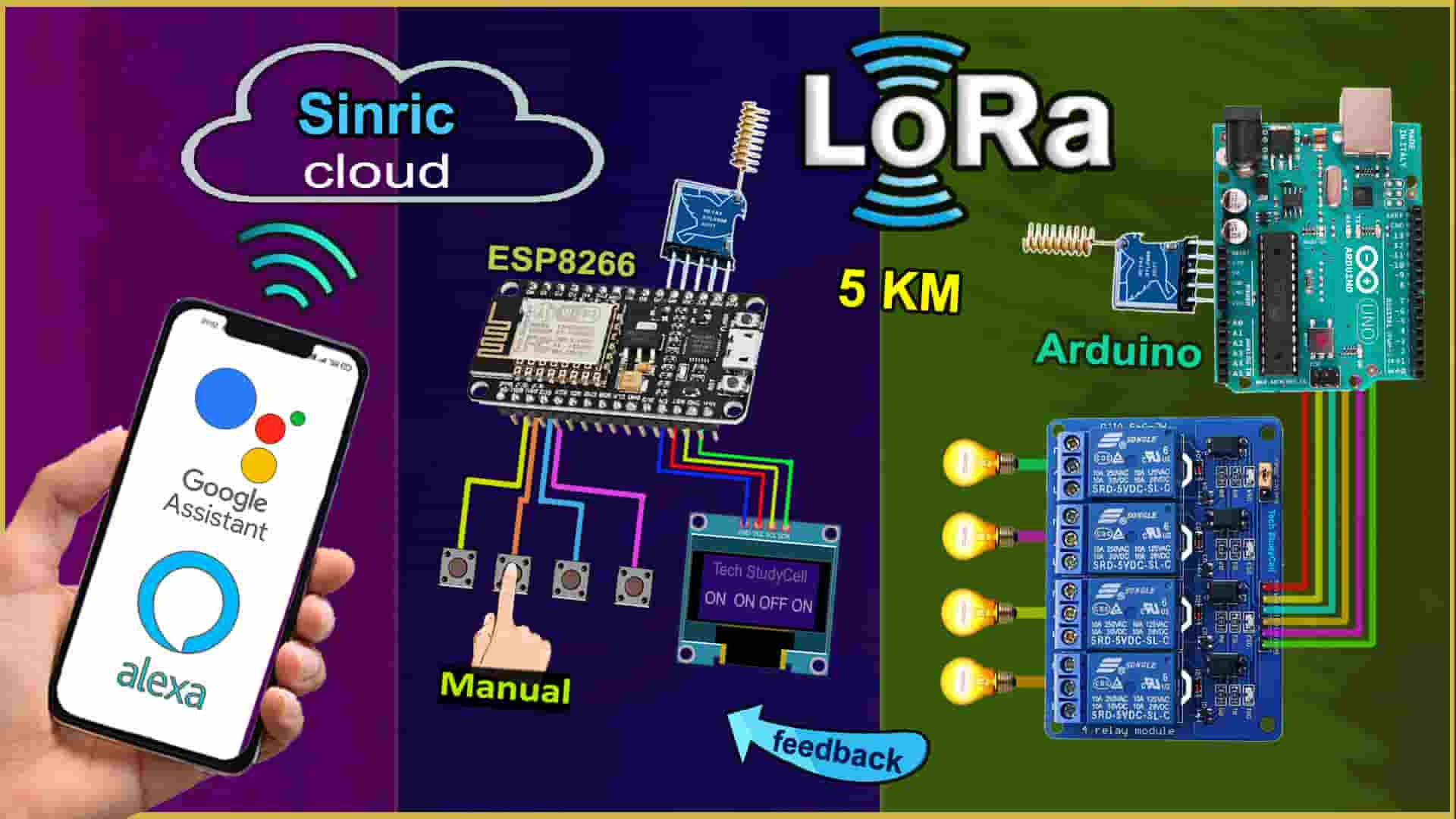
In this Lora project, I have shown how to make a Lora ESP8266 Arduino IoT project with Google Assistant and Alexa. Explained both the transmitter and receiver Lora circuit, source codes to control the relays, and monitor real-time feedback with the Google Home and Amazon Alexa IoT platform.

Lora WiFi project to control any appliances from anywhere in the world. So this project is very useful in rural areas.
Table of Contents
Required Components for the LoRA IoT Project
Transmitter Lora ESP8266 circuit:
- Lora Module REYAX RYLR998 1no
- ESP8266 NodeMCU 1no
- 1k Resistors 2no
- 4.7k Resistor 1no
- 10k Resistor 1no
- 5-mm LED 2no
- 0.96″ OLED Display
- Push-buttons 5no

Receiver Lora Arduino circuit:
- Lora Module REYAX RYLR998 1no
- Arduino UNO 1no
- 5v 4-channel Relay Module 1no
- 1k Resistor 1no
- 2k Resistor 1no
- 4.7k Resistor 1no
- 5-mm LED 1no
- Push-Buttons or Switches 4no
Transmitter Lora circuit using ESP8266

In the transmitter LoRa circuit, I have used ESP8266 NodeMCU. Here I have made a voltage divider using 4.7k and 10k resistors to drop down the 5V logic level to the 3.3V logic level for the serial communication with the LoRa module.
For the serial communication with the LoRa module, I have used D7 as RX and D8 as TX with the SoftwareSerial library.
The pushbuttons are connected with the SD3, D3, D5, RX, and D6 GPIO pins of the NodeMCU. ( Here SD3, D3, D5, and RX are for controlling the relays, and D6 is used for requesting feedback from receiving side).
And the status LED is connected with the D4 pin.
You can use any 5V DC supply or 9V battery to supply the circuit.
Receiver Lora circuit using Arduino UNO

In the receiver LoRa circuit, I have used Arduino UNO. Also here I have made a voltage divider using 2k and 4.7k resistors to drop down the 5V logic level to the 3.3V logic level.
For the serial communication with the Lora module, I have used D2 as RX and D3 as TX with the SoftwareSerial library.
I have used D4, D5, D6 & D7 digital pins to control the 4-channel relay module.
And the GPIO D10, D11, D12 & D13 are connected with switches to control the relay module manually.
The LED is connected with the A3 pin.
As per the source code, when the control pins of the relay module receive the LOW signal the respective relay will turn on and the relay will turn off for the HIGH signal in the control pin.
I have used the INPUT_PULLUP function in Arduino IDE instead of using the pull-up resistors with each switch.
I have used a 5V 2Amp power supply to supply the Arduino UNO and relay module.
Please take the proper safety precautions while working with high voltage.
Tutorial video on Arduino ESP8266 LoRa Project
In the tutorial video, I have covered the following topics in detail.
- Demonstrated LoRa ESP8266 Arduino IoT project with Sinric Pro.
- Explained Transmitter & Receiver Lora circuits.
- Setup FREE Sinric Pro account for the LoRa ESP8266 project.
- Explained the source codes for this Lora Arduino project.
- Setup Google Home & Amazon Alexa apps for this IoT project.
- Control high voltage appliances with LoRa and voice assistant.
Important points of this Lora Project:
- The Network ID and BAND should be the same for the transmitter and receiving end Lora module.
- Set the BAND as per the eligible LoRa bands in your country.
- You can use any other microcontroller for this Lora project.
- All the AT commands for configuring the LoRa module are written in the void setup() function of the source code.
- The range for this LoRa project will be up to 5KM in rural areas. (Range will decrease if the number of obstacles increases in the signal path).
- After the restart, you have to wait till the STATUS LED turns OFF.
- Please watch the complete video, otherwise, you may face some issues.
Sinric Pro FREE account setup
For this smart house project, I have used the Sinric Pro Free account. First, you have to add 3 devices to the Sinric Pro account.

I have already explained, how to set up and add devices to Sinric Pro in the following article.
Download the Codes for the Lora IoT Project
Click on the following buttons to download the source codes for this Lora IoT project.
Here, I have used the SoftwareSerial library for the serial communication with the LoRa module. So do not disconnect the LoRa module from the microcontroller while uploading the code and during the booting process.
For this Lora project, you don’t have to separately configure the Lora modules. All the required AT commands are written in the void setup() function, which will execute after the booting process of the microcontroller.
Program ESP8266 NodeMCU with Arduino IDE
In the tutorial video, I explained all the steps to program the ESP8266 NodeMCU using Arduino IDE.
- Update the Preferences –> Aditional boards Manager URLs: https://dl.espressif.com/dl/package_esp32_index.json, http://arduino.esp8266.com/stable/package_esp8266com_index.json
- Then install the ESP8266 board from the Board manager or Click Here to download the ESP8266 board.
- Download the required libraries from the following links:
- Sinric Pro by Boris Jaeger (Download Sinric Pro examples for ESP8266 & ESP32)
- WebSockets by Markus Sattler (minimum Version 2.3.5)
- ArduinoJson by Benoit Blanchon (minimum Version 6.12.0)
- Adafruit_SSD1306 2.5.1 Library
Click Here to visit the GitHub page of Sinric Pro for more details.
**Please download the latest version of the libraries from the given links. Then install the libraries at Arduino IDE – Sketch – Include Library – Add Zip Library.
Enter the following details in the code for ESP8266
Enter the APP KEY, APP SECRET, Wi-Fi name, and Wi-Fi password in the code.
You can get the APP KEY and APP SECRET under the Credentials menu in Sinric Pro.
#define WIFI_SSID         "YOUR-WIFI-NAME"
#define WIFI_PASS         "YOUR-WIFI-PASSWORD"
#define APP_KEY           "YOUR-APP-KEY"
#define APP_SECRET        "YOUR-APP-SECRET"
Also, enter the device id in the code. You will find the Device IDs from the Devices menu.
//Enter the device IDs here
#define device_ID_1   "SWITCH_ID_NO_1_HERE"
#define device_ID_2   "SWITCH_ID_NO_2_HERE"
#define device_ID_3   "SWITCH_ID_NO_3_HERE"
#define device_ID_4   "SWITCH_ID_NO_4_HERE"
**When you add a device in Sinric Pro, a unique ID is assigned to that device. If you create 3 devices, then there will be 3 unique device IDs.
As I have used the free plan of the Sinric pro, so I have entered the 3-device IDs. (Sinric Pro gives 3 devices for FREE).
After that, define the Band, Network ID, Lora Module address, and Receiving end Lora address in the code.
String lora_band = "865000000"; //enter band as per your country
String lora_networkid = "5";    //enter Lora Network ID
String lora_address = "1";      //enter Lora address
String lora_RX_address = "2";   //enter Lora RX address
**You have to define the Lora band as per your country.
The Band and Network ID must be the same in both transmitting and receiving end Lora.

Program Arduino UNO with Arduino IDE
You need to download any library for this code.
After downloading just define the Band, Network ID, Lora Module address, and Receiving end Lora address in the code.
String lora_band = "865000000"; //enter band as per your country
String lora_networkid = "5";    //enter Lora Network ID
String lora_address = "2";      //enter Lora address
String lora_RX_address = "1";   //enter Lora TX address (for sending feedback)
**You have to define the Lora band as per your country.
After programming the NodeMCU and Arduino UNO, connect the 5V supply. then wait till both Status LEDs turn OFF.
It may take a few seconds as during this time NodeMCU or Arduino is configuring the LoRa module with AT commands.
PCB for the ESP8266 Transmitter LoRa circuit

Although the PCB is not mandatory, but if you want, you can also use this PCB to make the circuit compact and give the project a professional look.

About PCBWay and their services
You can order any custom design PCBs from PCBWay at very reasonable prices.
PCBWay not only produces FR-4 and Aluminum boards but also advanced PCBs like Rogers, HDI, Flexible and Rigid-Flex boards, at very affordable prices.
For the online instant quote page please visit – pcbway.com/orderonline
You can also explore different PCB projects from their Open-source community pcbway.com/project/.
For more details please visit the following articles.
Why PCBway
PCB Capabilities
High-Quality PCB
Steps to order PCB from PCBWay
To order the PCB first visit PCBWay.com.

Then enter the following details:
- PCB Size (Length & Width) in mm & PCB quantity
- Select masking color for the PCB
- Select country and shipping method
- Click on the “Save to Cart” button

Now click on the “Add Gerber Files” to upload the PCB Gerber file.
Then click on the “Submit Order Now” to place the order.
After that, they will review the Gerber file and accordingly confirm the order.
I have used their services for my different home automation projects, I always received the PCB on time and the quality is very good in this price range.
Required Components for the PCB
- REYAX RYLR998 or RYLR896 Lora Module 1no
- ESP8266 NodeMCU 1no
- 1k Resistors 2no
- 4.7k Resistor 1no
- 10k Resistor 2no
- 5-mm LED 2no
- Push-button 6no
- Jumper 2no
- Terminal connector 2 pin 1no
- 0.96″ OLED Display
Setup Google Home & Amazon Alexa app
After uploading the code to ESP-01, please refer to the following articles for connecting the Sinric Pro Account with Amazon Alexa and Google Home App.
After doing all these steps, now you control the appliances with Google Assistant and Alexa.
Google Assistant & Alexa control Relays

You can ask Google Assistant, to turn on the light [“Hey Google, Turn ON the Outdoor Light“]. Thus, you can control the appliances with voice commands using Google Assistant
And also monitor the real-time feedback in the Google Home App.

You can also ask Alexa, to turn on the light [“Alexa, Turn ON Outdoor Light“]. Thus, you can control the appliances with voice commands using Amazon Alexa App
And also monitor the real-time feedback in the Amazon Alexa App (No ECHO DOT device required).
Control relay with LoRa & Manual switches

You can also control the relays from the transmitter Lora circuit as shown in the picture. You can also monitor the feedback on OLED.
If the NodeMCU is connected with the WiFi, then you can monitor the feedback from the smartphone.

You can also control the appliances from manual switches or pushbuttons.
To get the feedback you have to press the STATUS button.
Please watch the complete tutorial video for all the details.
Click Here for more such ESP8266 projects.
Please do share your feedback on this IoT project. Thank you for your time.


