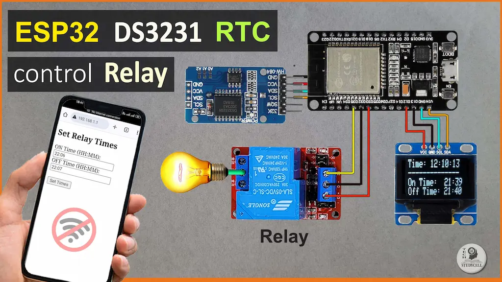
In this ESP32 project, I have shown how to make an ESP32 DS3231 RTC timer control relay with an OLED clock. You can set the ON/OFF time for the relay using the ESP32 access point. This project doesn’t need any WiFi connection.

The ESP32 will get the time from the DS3231 module and display the time on the OLED along with the ON/OFF time for the relay.
The DS3231 is a highly accurate real-time clock (RTC) module designed for use in timekeeping applications.

You can connect to the ESP32 Access Point using a fixed IP address to adjust the relay’s ON/OFF times. Once connected to the Wi-Fi network created by the ESP32, you can access a web interface by entering the IP address 192.168.1.1 into your web browser. This interface allows you to set the specific times when the relay should turn on and off. This setup provides a convenient way to manage the relay schedule remotely without reprogramming the ESP32.
Table of Contents
Required Components for ESP32 Project:

- ESP32 DevKIT V1 Amazon
- DS3231 RTC module
- 1-channel 5V SPDT Relay Module Amazon
- OLED
- PM05 5V AC to DC converter
Circuit of the ESP32 DS3231 RTC Timer Relay
Now it’s time to assemble the hardware. Connect the ESP32, DS3231 RTC module, Relay Module, OLED Display, and Manual Switch according to the circuit diagram below.

I have used D25 GPIO to control the relay module.
The DS3231 module and OLED (optional) are connected with D22 & D21 GPIO.
You can also use a 5V 5Amp mobile charger to supply the circuit instead of AC to DC converter.
For manual control, you can also connect a 5A latched switch across the COM & NO terminal of the relay.
Please take proper safety precautions while connecting the AC appliances.
Tutorial video on ESP32 RTC Project
In the ESP32 tutorial video, I covered the following topics.
- Explained the source code for the ESP32 DS3231 RTC control relay.
- How to set ON/OFF time using ESP32 Access Point.
- Control the relay using ESP32 RTC Timer.
PCB for this ESP32 DS3231 Project

You can also use the following PCB for this ESP32 project.
Now you can easily order your own custom-designed PCB from PCBWay at very reasonable prices.

PCBWay not only produces FR-4 and Aluminum boards but also advanced PCBs like Rogers, HDI, and Flexible and Rigid-Flex boards, at very affordable prices.
For the online instant quote page please visit – pcbway.com/orderonline
You can also explore different PCB projects from their Open-source community pcbway.com/project/.
For more details please visit the following articles.
Why PCBway
Program ESP32 with Arduino IDE
If the DS3231 RTC module is not configured, then you have to update the current time to the DS3231 module.
In the Tutorial video, I have explained all the steps to program the ESP32 using Arduino IDE.
- Update the Preferences –> Additional boards Manager URLs: https://dl.espressif.com/dl/package_esp32_index.json, http://arduino.esp8266.com/stable/package_esp8266com_index.json
- Then install the ESP32 board from the Board Manager or Click Here to download the ESP32 board.
- Download the required libraries as mentioned in the code:
Code for the ESP32 Relay module
#include <Arduino.h>
#include <Wire.h>
#include <RTClib.h>
#include <WiFi.h>
#include <WiFiClient.h>
#include <WebServer.h>
#include <Preferences.h>
#include <Adafruit_GFX.h>
#include <Adafruit_SSD1306.h> // Include the SSD1306 library

#define RELAY_PIN 25  // Define the pin to which the relay is connected

#define SCREEN_WIDTH 128 // OLED display width, in pixels
#define SCREEN_HEIGHT 32 // OLED display height, in pixels
#define OLED_RESET    -1 // Reset pin # (or -1 if sharing Arduino reset pin)


RTC_DS3231 rtc;    // Create an instance of RTC_DS3231
Preferences preferences;

WebServer server(80);

int onHour;
int onMinute;
int offHour;
int offMinute;

Adafruit_SSD1306 display(SCREEN_WIDTH, SCREEN_HEIGHT, &Wire, OLED_RESET); // Initialize the SSD1306 display

// Embedded HTML content
const char index_html[] PROGMEM = R"rawliteral(
<!DOCTYPE html>
<html>
<head>
  <title>Set Relay Times</title>
</head>
<body>
  <h2>Set Relay Times</h2>
  <form action="/set" method="POST">
    ON Time (HH:MM):<br>
    <input type="text" name="onTime"><br>
    OFF Time (HH:MM):<br>
    <input type="text" name="offTime"><br><br>
    <input type="submit" value="Set Times">
  </form>
</body>
</html>
)rawliteral";

void handleRoot() {
  server.send(200, "text/html", index_html);
}

void handleSet() {
  String onTime = server.arg("onTime");
  String offTime = server.arg("offTime");

  // Parse ON and OFF times
  onHour = onTime.substring(0, 2).toInt();
  onMinute = onTime.substring(3).toInt();
  offHour = offTime.substring(0, 2).toInt();
  offMinute = offTime.substring(3).toInt();

  // Save the ON and OFF times to EEPROM
  preferences.begin("relay_settings", false);
  preferences.putUInt("onHour", onHour);
  preferences.putUInt("onMinute", onMinute);
  preferences.putUInt("offHour", offHour);
  preferences.putUInt("offMinute", offMinute);
  preferences.end();

  server.send(200, "text/html", "Times set successfully!");
}

void setup() {
  Serial.begin(9600);
  Wire.begin();
  rtc.begin();

  pinMode(RELAY_PIN, OUTPUT);
  digitalWrite(RELAY_PIN, HIGH);  // digitalWrite(RELAY_PIN, LOW); (for Active-HIGH Relay)

  // Initialize the OLED display
  if (!display.begin(SSD1306_SWITCHCAPVCC, 0x3C)) {
    Serial.println(F("SSD1306 allocation failed"));
    for (;;);
  }
  display.clearDisplay();

  // Set ESP32 as an access point with a fixed IP address
  WiFi.softAP("ESP32_AP", "password", 7); // SSID: ESP32_AP, Password: password, Channel: 7
  IPAddress ip(192, 168, 1, 1); // Set the IP address of the access point
  IPAddress gateway(192, 168, 1, 1);
  IPAddress subnet(255, 255, 255, 0);
  WiFi.softAPConfig(ip, gateway, subnet);

  // Print the IP address of the access point
  Serial.print("AP IP address: ");
  Serial.println(WiFi.softAPIP());

  // Read the ON and OFF times from EEPROM
  preferences.begin("relay_settings", true);
  onHour = preferences.getUInt("onHour", 8);
  onMinute = preferences.getUInt("onMinute", 0);
  offHour = preferences.getUInt("offHour", 18);
  offMinute = preferences.getUInt("offMinute", 0);
  preferences.end();

  // Print the stored ON and OFF times
  Serial.print("ON Time: ");
  print2digits(onHour);
  Serial.print(":");
  print2digits(onMinute);
  Serial.println();
  Serial.print("OFF Time: ");
  print2digits(offHour);
  Serial.print(":");
  print2digits(offMinute);
  Serial.println();

  server.on("/", handleRoot);
  server.on("/set", handleSet);

  server.begin();
  Serial.println("HTTP server started");
}

void loop() {
  server.handleClient();

  updateRelayState();

  // Display the current time, ON time, and OFF time on the OLED display
  displayData();

  delay(1000);
}

void displayData(){
  display.clearDisplay();
  display.setTextSize(1);
  display.setTextColor(SSD1306_WHITE);
  display.setCursor(0,0);
  DateTime now = rtc.now();
  display.print("Time: ");
  display.print(now.hour());
  display.print(":");
  display.print(now.minute());
  display.print(":");
  display.println(now.second());
  display.print("ON Time: ");
  display.print(onHour);
  display.print(":");
  display.println(onMinute);
  display.print("OFF Time: ");
  display.print(offHour);
  display.print(":");
  display.println(offMinute);
  display.println("http://192.168.1.1/");
  display.display();
}

void updateRelayState() {
  DateTime now = rtc.now();

  if (now.hour() == onHour && now.minute() == onMinute) {
    digitalWrite(RELAY_PIN, LOW); // digitalWrite(RELAY_PIN, HIGH); (for Active-HIGH Relay)
  } else if (now.hour() == offHour && now.minute() == offMinute) {
    digitalWrite(RELAY_PIN, HIGH); // digitalWrite(RELAY_PIN, LOW); (for Active-HIGH Relay)
  }
}

void print2digits(int number) {
  if (number < 10) {
    Serial.print("0");
  }
  Serial.print(number);
}
Here’s a short explanation of the basic workflow of the provided code:
- Library Inclusions and Definitions:
- Includes necessary libraries for RTC, Wi-Fi, web server, preferences storage, and OLED display.
- Defines constants for relay pin, screen dimensions, and OLED reset pin.
- Global Object and Variable Initialization:
- Initializes objects for RTC, preferences storage, web server, and OLED display.
- Defines variables to store relay ON and OFF times.
- HTML Content:
- Defines an HTML form as a string for setting the relay ON and OFF times.
- Web Server Handlers:
handleRoot(): Sends the HTML form to the client when they access the root URL.handleSet(): Processes the form submission, parses the times, stores them in preferences, and sends a success message to the client.
- Setup Function:
- Initializes serial communication, I2C bus, RTC, relay pin, and OLED display.
- Configures the ESP32 as a Wi-Fi access point.
- Reads stored relay ON and OFF times from preferences and prints them to the serial monitor.
- Sets up web server routes and starts the server.
- Main Loop:
- Continuously handles incoming HTTP requests with
server.handleClient(). - Updates the relay state based on the current time.
- Updates the OLED display with the current time and relay settings.
- Delays for 1 second before repeating.
- Helper Functions:
displayData(): Updates the OLED display with the current time and relay settings.updateRelayState(): Controls the relay based on the current time and stored ON/OFF times.print2digits(): Formats numbers to always show two digits for better readability in the serial output.
Workflow:
- Initialization:
- The
setup()function initializes all components, sets up the Wi-Fi access point, and reads stored relay times from preferences.
- Main Execution Loop:
- The
loop()function continuously:- Handles web server requests.
- Updates the relay state based on the RTC time.
- Updates the OLED display with the current time and relay settings.
- User Interaction:
- Users connect to the ESP32 access point and access the web form.
- Users input relay ON and OFF times and submit the form.
- The submitted times are processed, validated, and stored in preferences.
- The relay state and OLED display are updated accordingly.
This setup allows users to configure relay operation times through a web interface, with real-time feedback displayed on the OLED screen.
You have to always enter the ON/OFF time for the relay in 24H format (as shown).
Now upload the code to ESP32.

This display updates every second to reflect the current time and will show the configured ON and OFF times for the relay.
The URL “http://192.168.1.1/” is displayed, indicating the web address users can visit to set the relay times.
Steps to set the ON & OFF times for the relay
To set the ON and OFF times for the relay, follow these steps:
- Power on the ESP32 and Connect to the Access Point:

- Power on your ESP32 device.
- It will create a Wi-Fi access point with the SSID “ESP32_AP” and password “password“.
- Connect your computer or smartphone to this Wi-Fi network.
- Open the Web Browser and Access the Web Interface:
- Open a web browser on your connected device.
- Enter the IP address
http://192.168.1.1/in the address bar and press Enter.
- View the Web Form:
- Enter the ON and OFF Times:
- In the “ON Time (HH:MM)” field, enter the time you want the relay to turn ON (e.g.,
22:06). - In the “OFF Time (HH:MM)” field, enter the time you want the relay to turn OFF (e.g.,
22:07).
- Submit the Form:
- Click the “Set Times” button to submit the form.
- Confirmation:
- After submitting the form, you should see a confirmation message: “Times set successfully!”.
- The new ON and OFF times are now stored in the device’s preferences and will be used to control the relay.
- Check the OLED Display:
- The OLED display will update to show the new ON and OFF times along with the current time.

These steps allow you to configure the relay times using a user-friendly web interface provided by the ESP32.
Now the relay will automatically turn on according to the pre-defined ON and OFF times.

I hope you like this Smart house project idea with the Espressif ESP32.
Click Here for more such ESP32 projects.
Please do share your feedback on this IoT project. Thank you for your time.


