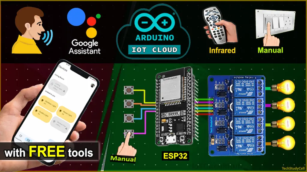
In this smart home IoT project, I have explained how to make an Arduino Cloud ESP32 home automation system to control appliances with the internet from anywhere in the world.
With this Internet of Things project, you can control 4 relays from the Arduino IoT Cloud dashboard, Google Home/Alexa app, IR remote, and manual switches. You can also monitor the real-time room temperature in the Arduino cloud dashboard and Google Home or Amazon Alexa app.
If there is no internet available still, you can control the appliances from the IR remote and switches.
I have used all the FREE tools and you don’t need any Alexa devices or Amazon Echo Dot for this voice control smart home IoT project.

So if you follow all the steps, you can easily make this Home Automation System with Arduino IoT Cloud and ESP32 for your home.
Table of Contents
Required Components for the ESP32 IoT projects

- ESP32 DevKIT V1 Amazon
- 4-channel 5V SPDT Relay Module Amazon
- DHT11 Sensor Amazon
- TSOP1838 IR Receiver (with metallic case) Amazon
- Latched Switch Amazon
- Any IR Remote
Circuit of the Arduino Cloud ESP32 projects

The circuit is very simple, I have used D23, D19, D18 & D5 GPIO to control the 4-channel relay module.
And, the GPIO D13, D12, D14 & D27 are connected with switches to control the relay module manually.
I have used the INPUT_PULLUP function in Arduino IDE instead of using the pull-up resistors with each push button.
As per the source code, when the control pins of the relay module receive a LOW signal the relay will turn on and the relay will turn off for the HIGH signal in the control pin.
IR remote receiver (TSOP1838) connected with D35. And the DHT11 sensor is connected to D4.
If you want to use the pushbuttons instead of latched switches, then just connect the pushbuttons instead of the switches across GPIO pins and GND.
I have used a 5V 5Amp mobile charger to supply the circuit.
Please take proper safety precautions while connecting the AC appliances.
In the Arduino Cloud tutorial, I have covered the following steps in detail.
- Create new things in Arduino IoT Cloud.
- How to set up Arduino IoT Cloud Dashboard.
- How to set up Arduino IoT Cloud for ESP32.
- Programming the ESP32 with Arduino IDE
- Connect Arduino IoT Cloud with Google Home App.
- Control relays with IR remote
Arduino IoT Cloud FREE account setup
For this IoT project, I have used the Arduino Cloud Free plan.
First, you have to add ESP32 devices in Arduino IoT Cloud.
Then you have to add 4 Google/Alexa Compatible Light variables and 1 Temperature sensor variable to the Arduino Cloud Thing.

Please click on the following link for more details on Arduino IoT Cloud setup.
Getting Started with Arduino IoT Cloud
Important points for the ESP32 Internet of Things project:
- You can control maximum 5 relays or sensors with the Arduino IoT cloud FREE plan.
- The IR receiver sensor must have a metallic casing. Otherwise, you may face issues while trying to get the Hex code.
- You can either select Google Home or Alexa in Arduino IoT Cloud Smart home integration.
- You don’t need an Amazon Echo Dot or any other Google Nest devices for this project. But if you have you can use it.
- After compiling the code, you have to press and hold the BOOT button of ESP32 until the code starts uploading.
- You can also use Arduino Web Editor to program the ESP32.
- You will get real-time feedback if the ESP32 is connected to the internet.
- Use a stable 5V 5A DC power supply.
Program ESP32 with Arduino IDE
In the tutorial video, I have explained all the steps to program the ESP32 using Arduino IDE.
- Update the Preferences –> Aditional boards Manager URLs: https://dl.espressif.com/dl/package_esp32_index.json, http://arduino.esp8266.com/stable/package_esp8266com_index.json
- Then install the ESP32 board from the Board Manager or Click Here to download the ESP32 board.
- Download the required libraries from the following links:
- ArduinoIoTCloud version 1.0.2 by Arduino and all the dependencies.
- IRremote Library version 3.3.0 by Shirriff.
Go to Sketch -> Include Libraries -> Manage Libraries in Arduino IDE.

When you try to install the ArduinoIoTCloud library, it will ask you to install all the dependencies. Then Click on Install All.
Code for Arduino IoT Cloud ESP32 home automation
#include <ArduinoIoTCloud.h>
#include <Arduino_ConnectionHandler.h>
#include <DHT.h>
#include <IRremote.h>

const char DEVICE_LOGIN_NAME[]  = ""; //Enter DEVICE ID

const char SSID[]               = "";    //Enter WiFi SSID (name)
const char PASS[]               = "";    //Enter WiFi password
const char DEVICE_KEY[]         = "";    //Enter Secret device password (Secret Key)

#define DHTPIN              4 //D4  pin connected with DHT
#define IR_RECV_PIN         35 //D35 pin connected with IR Receiver IC

// define the GPIO connected with Relays and switches
#define RelayPin1 23  //D23
#define RelayPin2 19  //D19
#define RelayPin3 18  //D18
#define RelayPin4 5  //D5

#define SwitchPin1 13  //D13
#define SwitchPin2 12  //D12
#define SwitchPin3 14  //D14
#define SwitchPin4 27  //D27

#define wifiLed    2   //D2

// Uncomment whatever type you're using!
#define DHTTYPE DHT11     // DHT 11
//#define DHTTYPE DHT22   // DHT 22, AM2302, AM2321
//#define DHTTYPE DHT21   // DHT 21, AM2301


DHT dht(DHTPIN, DHTTYPE);
IRrecv irrecv(IR_RECV_PIN);
decode_results results;

int toggleState_1 = 0; //Define integer to remember the toggle state for relay 1
int toggleState_2 = 0; //Define integer to remember the toggle state for relay 2
int toggleState_3 = 0; //Define integer to remember the toggle state for relay 3
int toggleState_4 = 0; //Define integer to remember the toggle state for relay 4

// Switch State
bool SwitchState_1 = LOW;
bool SwitchState_2 = LOW;
bool SwitchState_3 = LOW;
bool SwitchState_4 = LOW;

float temperature1 = 0;
float humidity1   = 0;
int   reconnectFlag = 0;

void onLight1Change();
void onLight2Change();
void onLight3Change();
void onLight4Change();

CloudSwitch light1;
CloudSwitch light2;
CloudSwitch light3;
CloudSwitch light4;
CloudTemperatureSensor temperature;

void initProperties(){

  ArduinoCloud.setBoardId(DEVICE_LOGIN_NAME);
  ArduinoCloud.setSecretDeviceKey(DEVICE_KEY);
  ArduinoCloud.addProperty(light1, READWRITE, ON_CHANGE, onLight1Change);
  ArduinoCloud.addProperty(light2, READWRITE, ON_CHANGE, onLight2Change);
  ArduinoCloud.addProperty(light3, READWRITE, ON_CHANGE, onLight3Change);
  ArduinoCloud.addProperty(light4, READWRITE, ON_CHANGE, onLight4Change);
  ArduinoCloud.addProperty(temperature, READ, 8 * SECONDS, NULL); //Update temperature value after every 8 seconds
}

WiFiConnectionHandler ArduinoIoTPreferredConnection(SSID, PASS);


void readSensor(){

  float h = dht.readHumidity();
  float t = dht.readTemperature(); // or dht.readTemperature(true) for Fahrenheit

  if (isnan(h) || isnan(t)) {
    Serial.println("Failed to read from DHT sensor!");
    return;
  }
  else {
    humidity1 = h;
    temperature = t;
   // Serial.println(tempareture);
  }
}

void sendSensor()
{
  readSensor();
}

void ir_remote_control(){
  if (irrecv.decode(&results)) {

      switch(results.value){
          case 0x80BF49B6:  relayOnOff(1); light1 = toggleState_1; break; //update the HEX-code
          case 0x80BFC936:  relayOnOff(2); light2 = toggleState_2; break; //update the HEX-code
          case 0x80BF33CC:  relayOnOff(3); light3 = toggleState_3; break; //update the HEX-code
          case 0x80BF718E:  relayOnOff(4); light4 = toggleState_4; break; //update the HEX-code
          default : break;
        }
        //Serial.println(results.value, HEX);
        irrecv.resume();
  }
}

void relayOnOff(int relay) {

  switch (relay) {
    case 1:
      if (toggleState_1 == 0) {
        digitalWrite(RelayPin1, LOW); // turn on relay 1
        toggleState_1 = 1;
        Serial.println("Device1 ON");
      }
      else {
        digitalWrite(RelayPin1, HIGH); // turn off relay 1
        toggleState_1 = 0;
        Serial.println("Device1 OFF");
      }
      delay(100);
      break;
    case 2:
      if (toggleState_2 == 0) {
        digitalWrite(RelayPin2, LOW); // turn on relay 2
        toggleState_2 = 1;
        Serial.println("Device2 ON");
      }
      else {
        digitalWrite(RelayPin2, HIGH); // turn off relay 2
        toggleState_2 = 0;
        Serial.println("Device2 OFF");
      }
      delay(100);
      break;
    case 3:
      if (toggleState_3 == 0) {
        digitalWrite(RelayPin3, LOW); // turn on relay 3
        toggleState_3 = 1;
        Serial.println("Device3 ON");
      } else {
        digitalWrite(RelayPin3, HIGH); // turn off relay 3
        toggleState_3 = 0;
        Serial.println("Device3 OFF");
      }
      delay(100);
      break;
    case 4:
      if (toggleState_4 == 0) {
        digitalWrite(RelayPin4, LOW); // turn on relay 4
        toggleState_4 = 1;
        Serial.println("Device4 ON");
      }
      else {
        digitalWrite(RelayPin4, HIGH); // turn off relay 4
        toggleState_4 = 0;
        Serial.println("Device4 OFF");
      }
      delay(100);
      break;
    default : break;
  }
}

void manual_control()
{
  if (digitalRead(SwitchPin1) == LOW && SwitchState_1 == LOW) {
    digitalWrite(RelayPin1, LOW);
    toggleState_1 = 1;
    SwitchState_1 = HIGH;
    light1 = toggleState_1;
    Serial.println("Switch-1 on");
  }
  if (digitalRead(SwitchPin1) == HIGH && SwitchState_1 == HIGH) {
    digitalWrite(RelayPin1, HIGH);
    toggleState_1 = 0;
    SwitchState_1 = LOW;
    light1 = toggleState_1;
    Serial.println("Switch-1 off");
  }
  if (digitalRead(SwitchPin2) == LOW && SwitchState_2 == LOW) {
    digitalWrite(RelayPin2, LOW);
    toggleState_2 = 1;
    SwitchState_2 = HIGH;
    light2 = toggleState_2;
    Serial.println("Switch-2 on");
  }
  if (digitalRead(SwitchPin2) == HIGH && SwitchState_2 == HIGH) {
    digitalWrite(RelayPin2, HIGH);
    toggleState_2 = 0;
    SwitchState_2 = LOW;
    light2 = toggleState_2;
    Serial.println("Switch-2 off");
  }
  if (digitalRead(SwitchPin3) == LOW && SwitchState_3 == LOW) {
    digitalWrite(RelayPin3, LOW);
    toggleState_3 = 1;
    SwitchState_3 = HIGH;
    light3 = toggleState_3;
    Serial.println("Switch-3 on");
  }
  if (digitalRead(SwitchPin3) == HIGH && SwitchState_3 == HIGH) {
    digitalWrite(RelayPin3, HIGH);
    toggleState_3 = 0;
    SwitchState_3 = LOW;
    light3 = toggleState_3;
    Serial.println("Switch-3 off");
  }
  if (digitalRead(SwitchPin4) == LOW && SwitchState_4 == LOW) {
    digitalWrite(RelayPin4, LOW);
    toggleState_4 = 1;
    SwitchState_4 = HIGH;
    light4 = toggleState_4;
    Serial.println("Switch-4 on");
  }
  if (digitalRead(SwitchPin4) == HIGH && SwitchState_4 == HIGH) {
    digitalWrite(RelayPin4, HIGH);
    toggleState_4 = 0;
    SwitchState_4 = LOW;
    light4 = toggleState_4;
    Serial.println("Switch-4 off");
  }
}

void doThisOnConnect(){
  /* add your custom code here */
  Serial.println("Board successfully connected to Arduino IoT Cloud");
  digitalWrite(wifiLed, HIGH); //Turn off WiFi LED
}
void doThisOnSync(){
  /* add your custom code here */
  Serial.println("Thing Properties synchronised");
}

void doThisOnDisconnect(){
  /* add your custom code here */
  Serial.println("Board disconnected from Arduino IoT Cloud");
  digitalWrite(wifiLed, LOW); //Turn off WiFi LED
}

void setup() {
  // Initialize serial and wait for port to open:
  Serial.begin(9600);
  // This delay gives the chance to wait for a Serial Monitor without blocking if none is found
  delay(1500);

  // Defined in thingProperties.h
  initProperties();
  dht.begin();
  irrecv.enableIRIn(); // Start the receiver
  // Connect to Arduino IoT Cloud
  ArduinoCloud.begin(ArduinoIoTPreferredConnection);

  ArduinoCloud.addCallback(ArduinoIoTCloudEvent::CONNECT, doThisOnConnect);
  ArduinoCloud.addCallback(ArduinoIoTCloudEvent::SYNC, doThisOnSync);
  ArduinoCloud.addCallback(ArduinoIoTCloudEvent::DISCONNECT, doThisOnDisconnect);

  setDebugMessageLevel(2);
  ArduinoCloud.printDebugInfo();

  pinMode(RelayPin1, OUTPUT);
  pinMode(RelayPin2, OUTPUT);
  pinMode(RelayPin3, OUTPUT);
  pinMode(RelayPin4, OUTPUT);

  pinMode(wifiLed, OUTPUT);

  pinMode(SwitchPin1, INPUT_PULLUP);
  pinMode(SwitchPin2, INPUT_PULLUP);
  pinMode(SwitchPin3, INPUT_PULLUP);
  pinMode(SwitchPin4, INPUT_PULLUP);

  //During Starting all Relays should TURN OFF
  digitalWrite(RelayPin1, HIGH);
  digitalWrite(RelayPin2, HIGH);
  digitalWrite(RelayPin3, HIGH);
  digitalWrite(RelayPin4, HIGH);
}

void loop() {

  ArduinoCloud.update();

  manual_control();     //Manual Control
  ir_remote_control();  //IR Remote Control
  sendSensor();         //Get Sensor Data
}

void onLight1Change() {
  //Control the device
  if (light1 == 1)
  {
    digitalWrite(RelayPin1, LOW);
    Serial.println("Device1 ON");
    toggleState_1 = 1;
  }
  else
  {
    digitalWrite(RelayPin1, HIGH);
    Serial.println("Device1 OFF");
    toggleState_1 = 0;
  }
}

void onLight2Change() {
  if (light2 == 1)
  {
    digitalWrite(RelayPin2, LOW);
    Serial.println("Device2 ON");
    toggleState_2 = 1;
  }
  else
  {
    digitalWrite(RelayPin2, HIGH);
    Serial.println("Device2 OFF");
    toggleState_2 = 0;
  }
}

void onLight3Change() {
  if (light3 == 1)
  {
    digitalWrite(RelayPin3, LOW);
    Serial.println("Device3 ON");
    toggleState_3 = 1;
  }
  else
  {
    digitalWrite(RelayPin3, HIGH);
    Serial.println("Device3 OFF");
    toggleState_3 = 0;
  }
}

void onLight4Change() {
  if (light4 == 1)
  {
    digitalWrite(RelayPin4, LOW);
    Serial.println("Device4 ON");
    toggleState_4 = 1;
  }
  else
  {
    digitalWrite(RelayPin4, HIGH);
    Serial.println("Device4 OFF");
    toggleState_4 = 0;
  }
}
After uploading the code to ESP32, please refer to the following articles for connecting the Arduino IoT Cloud Account with Google Home or Amazon Alexa App.
After doing all these steps, now you control the appliances either with Google Assistant or Alexa as per the configuration in Arduino IoT Cloud.
PCB for the ESP32 IoT Projects

You can also use this PCB for this ESP32 IoT project. Just download the Gerber file and order the PCB from PCBWay.

PCBWay is celebrating its 10th anniversary with a range of exciting new features and a variety of discount coupons.

This is a great opportunity to take advantage of special offers and explore everything they have to offer. Don’t miss out—visit the following link to discover more and start saving!
https://www.pcbway.com/activity/anniversary10th.html
Control Relay with Google Assistant or Alexa app


If the ESP32 is connected with WiFi, then you can ask Alexa, to turn on the light [“Alexa, Turn ON Room Light”]. Thus, you can control appliances like lights, fans, etc with voice commands using the Amazon Alexa App from anywhere in the world.
You can also monitor the real-time feedback and room temperature in the Google Home or Amazon Alexa app.
Control Relays with Arduino IoT Cloud Remote App
You can also control the relays and monitor the room temperature from the Arduino IoT Cloud Remote App.
Just download and install the Arduino IoT Cloud Remote app from Google Play Store or App Store, then log in to your Arduino Cloud account and select the dashboard.
Control Relays with Switches or IR Remote


You can always control the appliances manually with switches or an IR remote. and if the ESP32 is not connected to the Wi-Fi, still you can control the appliances with switches or an IR remote.
For IR remote control, first, you have to get the HEX codes of the remote buttons, then update the HEX code in the main source code. That’s it. Now you can control the appliances with that IR remote.


I hope you like this Smart House IoT project idea with the Arduino Cloud ESP32.
Click Here for more such ESP32 projects.
Please do share your feedback on this IoT project. Thank you for your time.


