In this Arduino ESP8266 project, I have explained how to make the Arduino home Automation project using an Atmega328 microcontroller and ESP01 wifi module.

This IoT based home automation system has the following features:
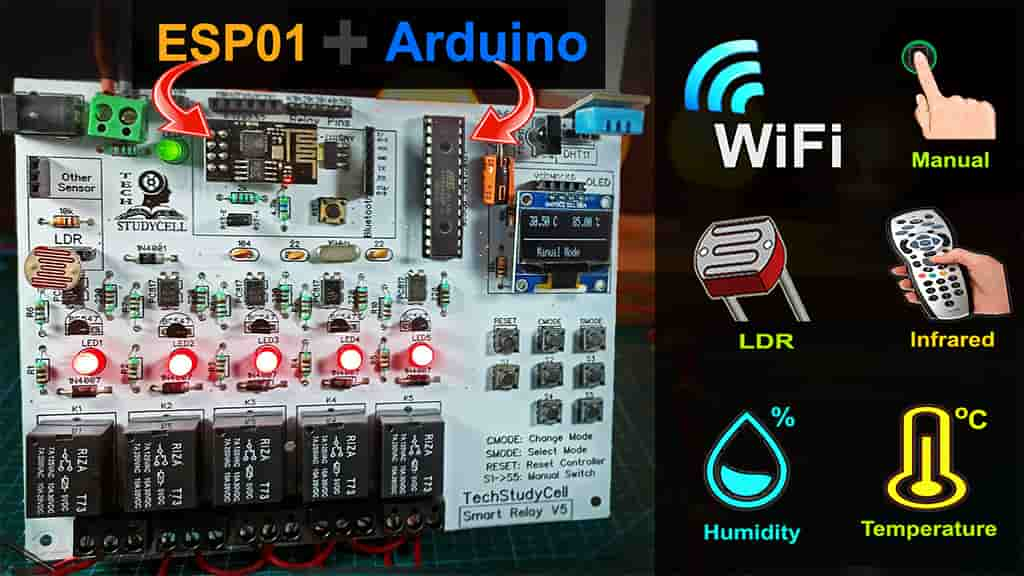
- Control Home appliances from the smartphone through the internet with Blynk App.
- Control Home appliances with manual switches.
- Control Home appliances with TV Remote (Infrared)
- Automatic LDR & temperature control relays.
- Monitor LIVE room temperature & humidity reading on the Blynk App and OLED display.
- Monitor real-time status of all switches on the Blynk App
- Inbuilt Arduino. Upload any Arduino sketch to the Atmega328P.
Table of Contents
Circuit Diagram of Arduino ESP8266 project


Required Components for Arduino Home Automation
- ATMEGA328P microcontroller with the bootloader installed
- ESP01 WiFi Module
- DHT11 Sensor
- 1738 Infrared Receiver IC
- BC547 NPN Transistors (5 no)
- PC817 Optocoupler (5 no)
- 1N4001 Diode (1 no)
- 1N4007 Diodes (5 no)
- LEDs 5mm (6 no)
- 22pF Capacitors (2 no)
- 100nF (104) Capacitor (1 no)
- 470uF 25V DC Capacitor (1 no)
- 220-ohm Resistors (15 no) (R1-R10)
- 1k Resistors (1 no)
- 10k Resistors (9 no)
- 2k (1no) & 4.7k (1no) Resistors
- LDR (1 no)
- 16MHz Crystal
- Push Buttons (9 no)
- 5V relays (5 no)
- Jumper (2no), connectors, IC base
- AMS1117 3.3V voltage regulator (1no)
- OLED Display 96″ (optional)
- FTDI 232 USB to Serial interface board or Arduino UNO
Tutorial video on this Arduino ESP01 control Relay
In this tutorial video, I have explained how to make this Arduino home automation using the atmga328p microcontroller and ESP01 wifi module.
Different Modes of Smart Relay
In this Smart home project you can control the home appliances in two modes:
- Manual Mode:
In manual mode, you can control the home appliances manually from Blynk App, pushbuttons & IR remote.
- Auto Mode:
In Auto Mode, the relay module can be controlled by predefined room temperature and ambient light sense by the DHT11 sensor and LDR.
To change the mode of relay module, you have to press the CMODE button.
Configuring the Blynk App

- Download the Blynk App from the Google play store or App store.
2. Tap on the new project and Enter the project name and choose the device ESP8266 as in this project I have used the ESP01 module.
3. After that Blynk will send an Auth Token to the registered email id. The Auth Token will be required while programming the ESP01.
Adding widgets in Blynk App

First open the project and tap on the “+” icon on the top.
Add 2 Gauge widgets from the widget box to show the temperature and humidity reading. I have used V5 and V6 pins.
Then add 5 Button widgets to control 5 relays. Here, I have used V1, V2, V3, V4 & V5 pins.
Then add 1 Styled button widget to change the Mode of the Smart Relay.
Please refer the tutorial video for configuring the Blynk App
Code for this Arduino Home Automation

For this Arduino home automation project you have to program both Atmega328P microcontroller and ESP01 wifi module.
I have explained the both codes in the tutorial video.
After downloading the code you have to unzip the file, then you will get the codes from Arduino (Code_Arduino_OLED0.96_SmartRelay_V5.ino) and the Code for ESP01 (Code_ESP8266_SmartRelay_V5.ino).
You can refer this articles on How to program ESP-01.
PCB for Arduino Home Automation

To give this home automation project a professional look and make the circuit compact, I have designed the PCB for this project.
You can also download the PCB Gerber file of this smart home project.
Soldering components on PCB

Now, places all the components on the PCB as mentioned on layout, then start soldering.
After soldering the components connect the Atmega328P and ESP01 with the circuit.
Connect Home Appliances with Relay

Now, connect 6 home appliances with the Arduino ESP01 control relay as per the circuit.
Please take proper safety precautions while working with the 110V or 220V supply.
Control Relays from Blynk App
If the ESP01 is connected with the WiFi, then you can control the home appliances from Blynk app. You can also monitor the LIVE room temperature and humidity reading in Blynk app.
Control Relays from Manual Switches

You can also use the push buttons to control the home appliances. If the ESP-01 is connected with WiFi then Blynk App will show the current status of the switches.
IR Remote control Relays

In this Arduino ESP8266 project, you can also use IR remote to control the home appliances.
Here, you have to map the Hex codes of IR remote in the Arduino Code. Please refer to the article on IR Remote control Relay.
Control Relays with Temperature & LDR

In this IoT-based home automation project, Arduino compares the predefined maximum and minimum temperature values with the temperature sensed by the DHT11 sensor.
You can set the temperature in the Arduino Code. as per the code in the Auto Mode, Relay-1 and Relay-2 will be controlled by the room temperature.

In a similar way, Relay-3 and Relay-4 can be controlled by the ambient light. You can set the parameter in the Arduino Sketch.
I hope you like this article on the Arduino ESP01 home automation system.
Please do share your feedback on this IoT project. Thank you for your time.


