In this Lora project, I have shown how to make LoRa IoT project using Arduino ESP8266 NodeMCU with real-time feedback. Explained both the transmitter and receiver circuit using the LoRa module and source code to control the relays with the Blynk IoT platform.

So if you follow all the steps, you can easily make this Lora WiFi project to control any appliances from anywhere in the world. So this project is very useful in rural areas.

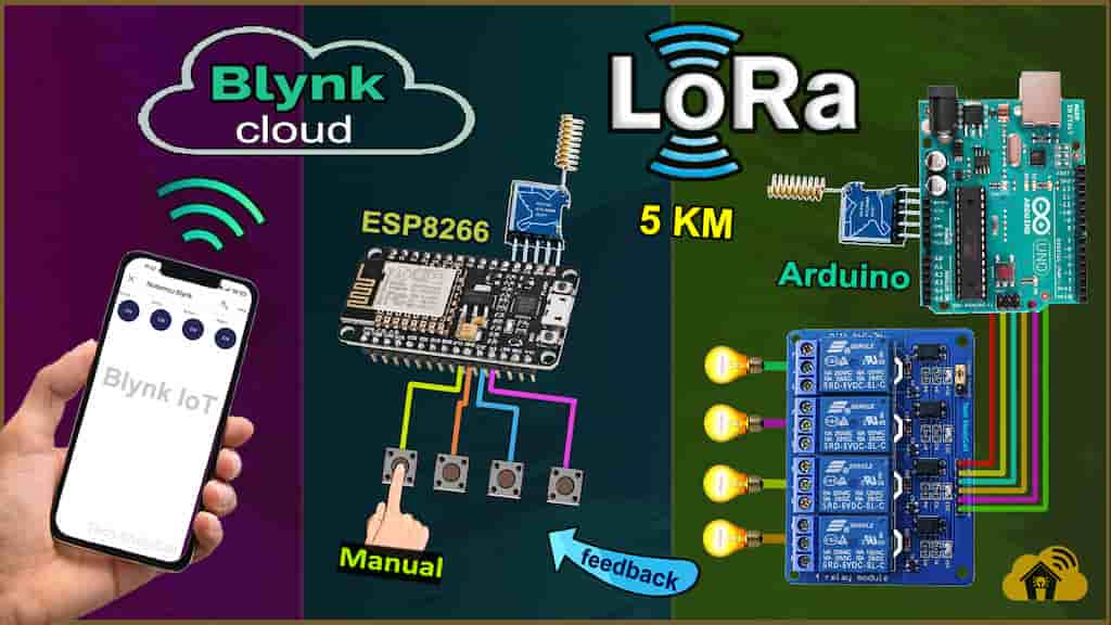
Here to control the appliances from smartphone, I have used the Blynk IoT application. This LoRa WiFi system works in the following steps.
- When you press any button in the Blynk IoT app, it sends the signal to Blynk cloud through the internet.
- Then the ESP8266 NodeMCU receives the signal from Blynk cloud through the internet.
- After that the ESP8266 will forward the same signal to Arduino through the LoRa.
- After receiving the signal through LoRa, Arduino will turn ON/OFF related relay and send the feedback to ESP8266 through the LoRa.
- After receiving the feedback the ESP8266 will turn ON the status LED and send the feedback to Blynk cloud.
- Then you can also monitor the real-time feedback in the Blynk IoT app.
Table of Contents
Required Components for the LoRA project
For Transmitter LoRa circuit
- Lora Module REYAX RYLR998 1no
- ESP8266 NodeMCU 1no
- 1k Resistors 2no
- 4.7k Resistor 1no
- 10k Resistor 1no
- 5-mm LED 2no
- Push button 4no
For Receiver LoRa Arduino circuit
- Lora Module REYAX RYLR998 1no
- Arduino UNO 1no
- 5V 4-channel Relay Module 1no
- 4.7k Resistor 1no
- 10k Resistor 1no
- 5-mm LED 1no
Transmitter Lora circuit using ESP8266 NodeMCU

In the transmitter LoRa circuit, I have used ESP8266 NodeMCU. Here I have made a voltage divider using 4.7k and 10k resistors to drop down 5V logic level to 3.3V logic level for the serial communication with the LoRa module.
For the serial communication with the LoRa module, I have used D7 as RX and D8 as TX with the SoftwareSerial library.
The pushbuttons are connected with the SD3, D3, D5, and RX GPIO pins of the NodeMCU.
And the status LED is connected with the D4 pin.
You can use any 5V DC supply or 9V battery to supply the circuit.
Receiver Lora circuit using Arduino UNO

In the receiver LoRa circuit, I have used Arduino UNO. Also here I have made a voltage divider using 4.7k and 10k resistors to drop down 5V logic level to 3.3V logic level.
I have used D4, D5, D6 & D7 digital pins to control the 4-channel relay module.
The LED is connected with the D13 pin.
As per the source code, when the control pins of the relay module receive the LOW signal the respective relay will turn on and the relay will turn off for the HIGH signal in the control pin.
I have used a 5V 2Amp power supply to supply the Arduino UNO and relay module.
Please take the proper safety precautions while working with high voltage.
Tutorial video on LoRa IoT using Arduino ESP8266
In the tutorial video, I have covered the following topics in detail.
- Explained Transmitter & Receiver LoRa circuit
- Setup Blynk cloud account for the LoRa ESP8266 circuit.
- Explained the codes for the LoRa IoT project.
- Setup Blynk IoT app for this home automation project.
- Control high voltage appliances with LoRa Arduino and Wi-Fi.
Set up Blynk IoT Cloud for the ESP8266
You can refer to the following article to set up the new Blynk cloud account
Getting started with New Blynk 2.0 IoT platform
Create Datastreams in Blynk cloud

Here, I have created 5 Datastreams. For the first 4 Datastreams (V1, V2, V3 & V4), the data type is Integer, MIN value is “0” and MAX value is “1”.
For the last Datastream (V5), the data type is String.
The web dashboard is optional in this IoT project.
Add Device in the new Blynk IoT platform
Steps to add device in Blynk IoT platform

First, go to Device, then click on “New Device“.

Click on “From template“.

Now select the Template which you have created for this Blynk project and give any device name.
Then click on “Create“.

After adding the device, go to “Device Info“.
In the “Device Info“, you will get the Blynk Auth Token, Template ID, and Device Name. All these details will be required in the code.
Codes for this LoRa project using ESP8266 and Arduino
Click on the following buttons to download the source codes for this LoRa project.

After downloading, you will get two codes (Transmitter & Receiver).
Upload the code for the transmitter circuit to NodeMCU and code for the receiver to Arduino UNO.
For the transmitter LoRa code, you have to update the Blynk Auth Token, Template ID, and Device Name.
#define BLYNK_TEMPLATE_ID ""
#define BLYNK_DEVICE_NAME ""
#define BLYNK_AUTH_TOKEN ""
Then enter the WiFi name (SSID) and WiFi password.
char ssid[] = "";
char pass[] = "";
Here, I have used the SoftwareSerial library for the serial communication with the LoRa module. So do not disconnect the LoRa module from the microcontroller while uploading the code and during the booting process.
AT commands used to configure the Lora modules
For this Lora project, you don’t have to separately configure the Lora modules. All the required AT commands are written in the void setup() function, which will execute after the booting process of the microcontroller.
For the Transmitter LoRa module
- AT+ADDRESS=1
- AT+NETWORKID=5
- AT+BAND=865000000
For the Receiver LoRa module
- AT+ADDRESS=2
- AT+NETWORKID=5
- AT+BAND=865000000
Here I have used the 865MHz band. Please enter the BAND as per the eligible LoRa band in your country.

After programming the NodeMCU, connect the 5V supply. then wait till the both blue LEDs (on board) turn ON and the status LED turn OFF.
It may take a few seconds as during this time NodeMCU is configuring the LoRa module with AT commands.
Set up Mobile Dashboard in Blynk IoT app

Steps to configure Mobile dashboard in Blynk IoT app.
- Open the Blynk IoT app, and select the Template.
- Tap on the 3-dash icon.
- Add 4 Buttons from the widget Box.
- Tap on each Button widget, then select the Datastream and the Mode will be “PUSH“.
- Then again tap on the 3-dash icon to add Value Display Widget.

- Now add the Value Display widget.
- Tap on the Value Display widget.
- Select the Datastream and front size.
- Exit from the SETUP/EDIT mode.
- Now the Blynk IoT app is ready for this LoRa WiFi project.
PCB for the ESP8266 Transmitter LoRa circuit
Although the PCB is not mandatory, but if you want, you can also use this PCB to make the circuit compact and give the project a professional look.
Control the appliances with Blynk IoT (Lora WiFi)

Now if the NodeMCU is connected with WiFi, you can control the appliance from the Blynk app. After receiving the feedback the Value Display widget will show “Feedback Received”. Otherwise, it will wait for feedback for a certain time, and after that, it will show “Feedback Not Received“.
Control relays from pushbutton through Lora

You can also control the relays from the pushbuttons as shown in the picture. After receiving the feedback the status LED will turn ON.
If the NodeMCU is connected with the Blynk cloud, then you can monitor the feedback in the Blynk app.
Please watch the complete tutorial video for all the details.
Click Here for more such ESP8266 projects.
Please do share your feedback on this IoT project. Thank you for your time.


