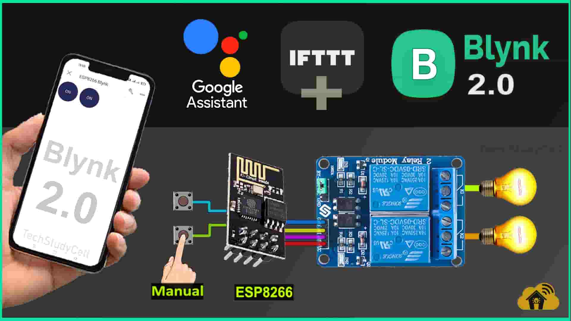
In this IoT project, I have explained how to make ESP01 ESP8266 projects using Blynk and Google Assistant to control relays with voice commands and manually with push buttons. You can also control the appliances from the Blynk IoT App and Blynk cloud web dashboard.

I have used the FREE plan of all the IFTTT and Blynk for this ESP01 home automation project.
So if you follow all the steps, you can easily make this IoT project with ESP8266 and Blynk app.
Table of Contents
Circuit of the Blynk ESP01 ESP8266 Projects

In the circuit, I have used GPIO-0 and GPIO-2 pins to control the 2-channel relay module.
And the GPIO-3 and GPIO-1 are connected with the pushbuttons to control the relay module manually.
I have used the INPUT_PULLUP function in Arduino IDE instead of using the pull-up resistors with each switch.
As per the source code, when the control pins of the relay module receive the LOW signal the respective relay will turn on and the relay will turn off for the HIGH signal in the control pin.
I have used a 5V 2Amp power supply to supply the circuit.
Required Components for the ESP8266 project

- ESP01 ESP8266
- 2-channel 5V SPDT Relay Module
- Pushbuttons
Blynk IoT Cloud setup

For this project, you have to create 2 Datastreams using V1 and V2 virtual pins to control 2 relays.
Please refer to the following article for the Blynk IoT Cloud account setup.
Getting started with New Blynk 2.0 IoT platform
Code for Blynk IoT Cloud ESP8266 home automation
After downloading the code, you will get 10 files. ( 1 .ino & 9 .h files). You have to keep all these files in the same folder.
Then open the .ino file in Arduino IDE, select the NodeMCU 1.0 board then compile the code. If you have downloaded all the required libraries then you should not get any errors.
In code, you have to update only the BLYNK_TEMPLATE_ID & BLYNK_DEVICE_NAME as shown in the video. You don’t have to enter the W-Fi credentials in the code.

Program ESP01 with Arduino IDE
In Arduino IDE, you have to download and install the ESP8266 board and Blynk Library.

Go to Sketch -> Include Libraries -> Manage Libraries in Arduino IDE, then search “Blynk”.
When you try to install the Blynk library, it may ask you to install all the dependencies. Then Click on Install All.
Please refer to this article for Programming ESP-01 using Arduino IDE.

After uploading the code, update the Wi-Fi credentials to ESP01 from the Blynk IoT app.
Connect Blynk with Google Assistant using IFTTT

In the following article, I have explained all the steps to connect Blynk with Google Assistant using the FREE IFTTT account.
Set up IFTTT to connect Blynk Project with Google Assistant
URL syntax to send web requests in the New Blynk IoT platform
Syntax: https://{server_address}/external/api/update?token={token}&{pin}={value}

The server region could be found in the right bottom corner of the web interface in the Blynk account.

In the server address, the first 4 characters are the Server Region.
Following are the server addresses for different regions.
- fra1.blynk.cloud – Frankfurt
- lon1.blynk.cloud – London
- ny3.blynk.cloud – New York
- sgp1.blynk.cloud – Singapore
- blr1.blynk.cloud – Bangalore
I have used the following Blynk URLs to send web requests from IFTTT to update the Datastreams values in the Blynk server.

To avoid any loose connections, I have used a PCB for this project. So get the PCB, you can download the Gerber file and order it from PCBWay.


About PCBWay and their services
You can order any custom design PCBs from PCBWay at very reasonable prices.
PCBWay not only produces FR-4 and Aluminum boards but also advanced PCBs like Rogers, HDI, Flexible, and Rigid-Flex boards, at very affordable prices.
For the online instant quote page please visit – pcbway.com/orderonline
You can also explore different PCB projects from their Open-source community pcbway.com/project/.
For more details please visit the following articles.
Why PCBway
PCB Capabilities
High-Quality PCB

If you use this PCB, then you can easily move to ESP01 program mode from the normal mode with a switch (as shown). In program mode, you can directly connect the FTDI232 USB to serial interface board to upload the code to the ESP-01 module.
Required Components for the PCB
- ESP01 ESP8266
- Relays 5v (SPDT) (2 no)
- BC547 Transistors (2 no)
- PC817 Optocuplors (2 no)
- 510-ohm 0.25-watt Resistor (2 no) (R1 — R2)
- 1k 0.25-watt Resistors (3 no) (R3 — R5)
- LED 5-mm (3 no)
- 1N4007 Diodes (2 no) (D1 — D2)
- Push Buttons (3 no)
- Terminal Connectors
- Jumper (2 no)
- Switch (1 no)
- 5V DC supply
ESP8266 ESP01 control Relays with Blynk App

If the ESP01 is connected with the Wi-Fi, then you can control the relays and monitor the real-time feedback from anywhere in the world using the Blynk IoT App.
Control Relays manually with Push Buttons

You can also manually control the appliances from the pushbuttons. If the ESP01 ESP8266 is connected to the internet then it will send real-time feedback to the Blynk Cloud.
Control Relays with Google Assistant

To control the relays with Google Assistant, just say the pre-defined voice commands. The Google Assistant will trigger the related IFTTT applet to send the web request to the Blynk cloud server.
I hope you like this IoT project idea with the new Blynk 2.0 IoT Cloud and ESP01 ESP8266.
Click Here for more such ESP8266 projects.
Please do share your feedback on this IoT project. Thank you for your time.


