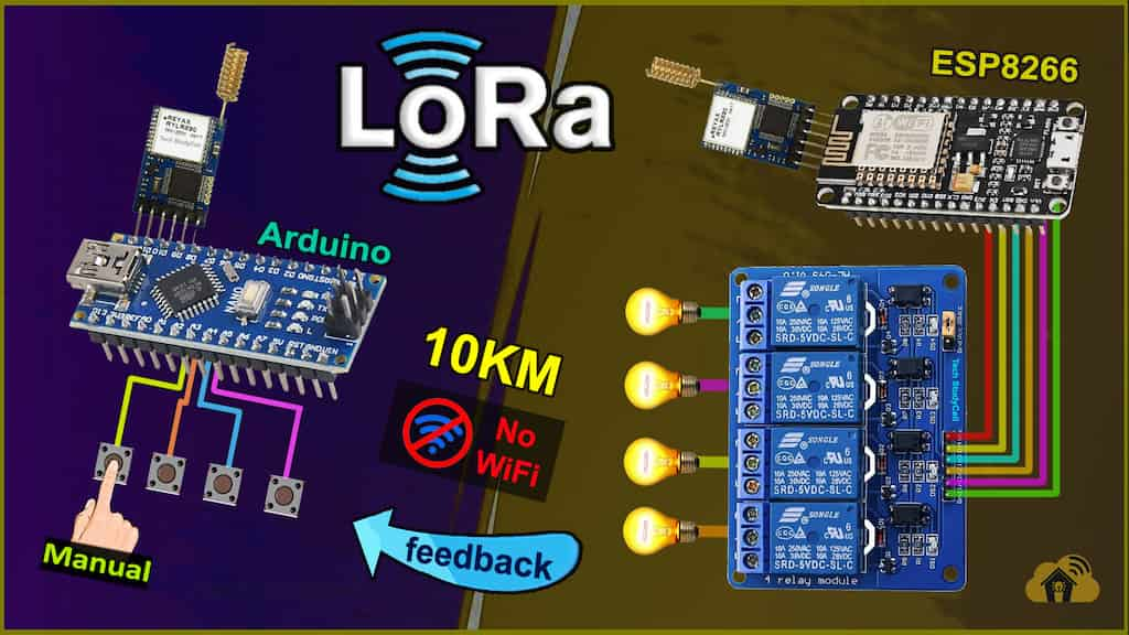
In this Lora project, I have shown how to make the LoRa Arduino ESP8266 control relay with real-time feedback using the RYLR896 LoRa module. Explained both the transmitter and receiving LoRa circuit and source codes and how to configure the LoRa modules with AT commands.

So if you follow all the steps, you can easily make this Lora Arduino project to control any appliances from 10KM away without Wi-Fi and Bluetooth. So this project is very useful in rural areas.
Table of Contents
Required Components for the LoRA project
For the Transmitter LoRa circuit

- REYAX RYLR896 Lora Module
- Arduino Nano
- 220-ohm Resistor
- 4.7k Resistor
- 10k Resistor
- 5-mm LED 3no
- Push buttons 4no
For the Receiving LoRa circuit

- REYAX RYLR896 Lora Module
- ESP8266 NodeMCU
- 5v 4-channel Relay Module
- 4.7k Resistor
- 10k Resistor
Transmitter Lora circuit using Arduino

In the transmitter LoRa circuit, I have used Arduino Nano. Here I have made a voltage divider using 4.7k and 10k resistors to drop down 5V logic level to 3.3V logic level.
The pushbuttons are connected with the D2, D3, D4, and D5 digital pins of the Arduino Nano.
And the LEDs are connected with D7, D8, and D13.
On the Arduino board, a resistor is already connected in series with the D13 pin, so I have not used any series resistor with the LED for the D13 pin.
You can use any 5V DC supply or 9V battery to supply the circuit.
Receiver Lora circuit using ESP8266

In the receiver LoRa circuit, I have used ESP8266 NodeMCU. Also here I have made a voltage divider using 4.7k and 10k resistors to drop down 5V logic level to 3.3V logic level.
I have used D1, D2, D5 & D6 GPIO pins to control the 4-channel relay module.
As per the source code, when the control pins of the relay module receive the LOW signal the respective relay will turn on and the relay will turn off for the HIGH signal in the control pin.
**The Boot will fail if RX is grounded during the Boot process. So connect the LoRa module after giving the supply to NodeMCU.
I have used a 5V 2Amp power supply to supply the NodeMCU and relay module.
Please take the proper safety precautions while working with high voltage.
Tutorial video on LoRa Arduino ESP8266 project
In the tutorial video, I have covered the following topics in detail.
- Demonstrate this ESP8266 Arduino Lora home automation project.
- Explained Transmitter & Receiver Lora circuit.
- Configure LoRa with AT commands.
- Explained the source codes for this LoRA project.
- Connecting the LoRa module with Arduino and ESP8266.
- Control high voltage appliances with LoRa.
Configuring the Parameters with AT commands

First, you have to connect the LoRa module with FTDI232 USB to serial interface board to configure some parameters with AT commands.
Please refer to the tutorial video for more details.
AT commands used for this Arduino Lora project
For the Transmitter LoRa module
- AT+ADDRESS=1
- AT+NETWORKID=5
- AT+BAND=865000000
For the Receiver LoRa module
- AT+ADDRESS=2
- AT+NETWORKID=5
- AT+BAND=865000000
Here I have used 865 MHz band. Please set the BAND as per the eligible LoRa band in your country.
Codes for this LoRa project using Arduino and ESP8266
Click on the following buttons to download the source codes for this LoRa project.

After downloading, you will get two codes (Transmitter & Receiver).
Upload the code for the transmitter circuit to Arduino Nano and code for the receiver to ESP8266 NodeMCU.
You can also use Arduino in the receiver circuit, for that update the GPIO in the receiving code.
If you use the same circuit, then no modification is required in the code.
Connect the LoRa module with Arduino and ESP8266

After uploading the code, connect the LoRa modules with the Arduino and NodeMCU.
For the receiving circuit turn ON the 5V supply before connecting the LoRa module.
PCB for the NodeMCU control Relays
Although the PCB is not mandatory, but if you want, you can also use this PCB to make the circuit compact and give the project a professional look.
Control the appliances with LoRa

Now, when you press the pushbutton in the transmitter circuit, the related relay should turn ON.
And after receiving the feedback from the receiver circuit the Green LED (D7) should turn on.
Please watch the complete tutorial video for all the details.
Click Here for more such ESP8266 projects.
Please do share your feedback on this IoT project. Thank you for your time.


