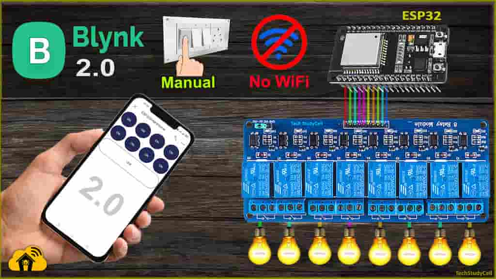
In this IoT project, I have explained how to make an IoT Smart Home Project using ESP32 Blynk to control 8 relays with the internet and manual switch. You can also monitor the real-time feedback in the Blynk app and if the Wi-Fi is not connected, then you can control the appliances manually with switches or push buttons.

I have used all the FREE tools for this ESP32 home automation project using Blynk IoT platform.
So if you follow all the steps, you can easily make this Smart Home project with ESP32 and Blynk app.
Table of Contents
Required Components for the IoT project

- ESP32 DEV KIT V1
- 8-channel 5V SPDT Relay Module
- Switches or Push Buttons
Circuit of the ESP32 IoT Smart Home Automation

The circuit is very simple, I have used D23, D22, D21, D19, D18, D5, D25 & D26 GPIO to control the 8-channel relay module.
And the GPIO D13, D12, D14, D27, D33, D32, D15 & D4 are connected with switches to control the relay module manually.
I have used the D2 (GPIO-2) pin as WiFi indicator. (D2 pin connected with the blue LED, mounted on ESP32 board)
I have used the INPUT_PULLUP function in Arduino IDE instead of using the pull-up resistors with each switch.
As per the source code, when the control pins of the relay module receive the LOW signal the relay will turn on and the relay will turn off for the HIGH signal in the control pin.
I have used a 5V 5Amp mobile charger to supply the circuit.
Tutorial video on ESP32 Blynk IoT Home Automation project
In the tutorial video, I have covered the following topics in detail.
- Set up Blynk cloud account, Web Dashboard.
- Update the Wi-Fi credentials to ESP32 through OTA.
- Setup Blynk IoT application Mobile Dashboard.
- Control relays from Blynk App and switches.
Control relays with the New Blynk IoT & Switches

You can control appliances with the New Blynk IoT app from anywhere in the world through the internet.
If the ESP32 is connected with WiFi, then you can also monitor the real-time feedback in the Blynk IoT app.

You can also control the appliances from manual switches.
If the ESP32 is connected with the Wi-Fi then it will send real-time feedback to the Blynk IoT server.
Blynk IoT Cloud setup for ESP32
Please refer to the following article for the Blynk IoT Cloud account setup.
Getting started with New Blynk 2.0 IoT platform
Program ESP32 with Arduino IDE
In the Tutorial video, I have explained all the steps to program the ESP32 using Arduino IDE.
- Update the Preferences –> Additional boards Manager URLs: https://dl.espressif.com/dl/package_esp32_index.json, http://arduino.esp8266.com/stable/package_esp8266com_index.json
- Then install the ESP32 board from the Board manager or Click Here to download the ESP32 board.
- Install all the required libraries in Arduino IDE:
- Install the Blynk Library (1.0.1) from Include Library or Click Here to download.

You can also install the libraries from the following path in Arduino IDE:
Sketch -> Include Libraries -> Manage Libraries.
When you try to install the Blynk library, it may ask you to install all the dependencies. Then Click on Install All.
Code for Blynk IoT Cloud ESP32 home automation
Click on the following buttons to download the source codes for this ESP32 project.
Modify the main code for this IoT based project

After downloading the code, you will get total 10 files. ( 1 .ino & 9 .h files). You have to keep all these files in the same folder.
Then open the .ino file in Arduino IDE, select the DOIT ESP32 DEVKIT V1 board then compile the code. If you have downloaded all the required libraries then you should not get any error.

In code, you have to update only the BLYNK_TEMPLATE_ID & BLYNK_DEVICE_NAME as shown in the video. You don’t have to enter the W-Fi credentials in the code.
After doing these changes, go to Tools and select the board as “DOIT ESP32 DEVKIT V1” and the proper PORT in Arduino IDE.
Then click on the upload button to program the ESP32 board.
In the tutorial video, I have explained, how to update Wi-Fi credentials from Blynk IoT app.
PCB for this ESP32 Home Automation system

To make the circuit compact, I have designed a PCB for this ESP32 project.
If you want, you can also use this PCB to make the circuit compact and give the project a professional look. This PCB can be used for any ESP32 Home Automation project.
Connect Home Appliances with Relay Module

Connect the home appliances with the relay module as per the circuit diagram.
Now, turn on the 5V DC supply and 110V/220V AC supply.
Our ESP32 Blynk Home Automation system is now ready

Now you can control the appliances from your smartphone, and manual switches.
Click Here for more such ESP32 projects.
Please do share your feedback on this IoT project. Thank you for your time.


