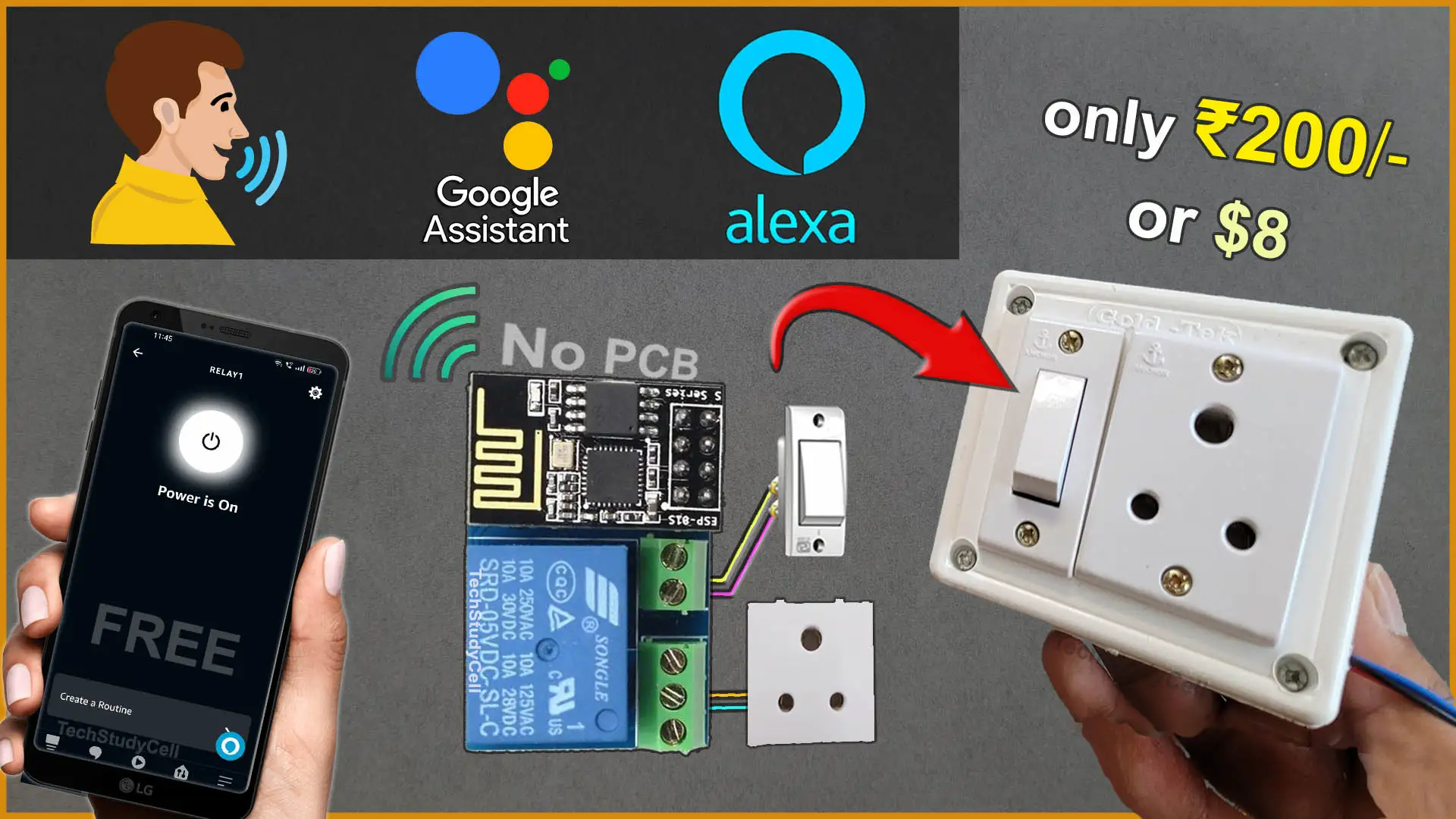
In this IoT project, I’ve explained how to create a basic IoT project using the ESP-01 module. You’ll need an ESP-01/01s relay v4.0 and ESP01 to make this home automation system work with Sinric, Alexa, Google Assistant, and a manual switch.


I have used the FREE plan of the Sinric Pro IoT platform for this ESP01 home automation project. You can buy the “ESP-01/01s relay v4.0” from any online store.
So if you follow all the steps, you can easily make this IoT project with ESP-01 ESP8266 and Sinric Pro.
Table of Contents
Required Components:

Circuit of the ESP01 Relay IoT project

In the circuit, you can use any 5V DC power supply.
The switch is wired between the NO and COM terminals of the relay. Since the switch isn’t directly linked to the ESP01, real-time feedback monitoring isn’t possible.
The relay control pin is connected to the GPIO-0 of the ESP-01.
Instead of the socket, you can also connect a lamp with the relay as per the following circuit.

Please take proper safety precautions while connecting the AC appliances.
Tutorial video on ESP01 IoT Project
In the ESP01 tutorial video, I covered the following topics.
- Explained the circuit for Programming the ESP01 using FTDI232.
- How to configure the Sinric Pro for ESP8266.
- How to generate source code using Zero Code features of Sinric.
- Upload the Auto-generated code to ESP01.
- Circuit for connecting all the components with ESP01 relay.
- Add the device to the Google Home app.
- Add the device to the Amazon Alexa app.
Circuit for Programming ESP01
Please refer to this article for Programming ESP-01 using Arduino IDE.

Connect the GPIO-0 with GND and press the RESET button to enter programming mode.
Configure Sinric Pro for ESP8266

For this ESP8266 project, I have used the Sinric Pro Free account. First, you have to add devices to the Sinric Pro account.
I have already explained, how to set up and add devices to Sinric Pro in the following article.
PCB for the ESP01 project
Although you can buy the readymade PCB from an online store, but to add more features to this circuit, you can design your own PCB like the following.

You can order any custom-designed PCBs from PCBWay at very reasonable prices.

PCBWay not only produces FR-4 and Aluminum boards but also advanced PCBs like Rogers, HDI, and Flexible and Rigid-Flex boards, at very affordable prices.
For the online instant quote page please visit – pcbway.com/orderonline
You can also explore different PCB projects from their Open-source community pcbway.com/project/.
For more details please visit the following articles.
Why PCBway
Program ESP8266 with Arduino IDE
In the Tutorial video, I have explained all the steps to program the ESP8266 using Arduino IDE.
- Update the Preferences –> Aditional boards Manager URLs: https://dl.espressif.com/dl/package_esp32_index.json, http://arduino.esp8266.com/stable/package_esp8266com_index.json
- Then install the ESP8266 board from the Board Manager or Click Here to download the ESP8266 board.
- Download the required libraries from the following links:
- Sinric Pro by Boris Jaeger (Download Sinric Pro examples for ESP8266 & ESP32)
- WebSockets by Markus Sattler (Minimum Version 2.3.5)
- ArduinoJson by Benoit Blanchon (Minimum Version 6.12.0)
Click Here to visit the GitHub page of Sinric Pro for more details.
**Please download the latest version of the libraries from the given links. Then install the libraries at Arduino IDE – Sketch – Include Library – Add Zip Library.
In this project, I have used the “Zero Code” features of the Sinric Pro to generate the source code. Please refer to the related tutorial video for the steps.

Code for the ESP01 Relay module
#ifdef ENABLE_DEBUG
   #define DEBUG_ESP_PORT Serial
   #define NODEBUG_WEBSOCKETS
   #define NDEBUG
#endif

#include <Arduino.h>
#if defined(ESP8266)
  #include <ESP8266WiFi.h>
#elif defined(ESP32) || defined(ARDUINO_ARCH_RP2040)
  #include <WiFi.h>
#endif

#include "SinricPro.h"
#include "SinricProSwitch.h"


#define WIFI_SSID         "YOUR-WIFI-NAME"
#define WIFI_PASS         "YOUR-WIFI-PASSWORD"
#define APP_KEY           "YOUR-APP-KEY"      // Should look like "de0bxxxx-1x3x-4x3x-ax2x-5dabxxxxxxxx"
#define APP_SECRET        "YOUR-APP-SECRET"   // Should look like "5f36xxxx-x3x7-4x3x-xexe-e86724a9xxxx-4c4axxxx-3x3x-x5xe-x9x3-333d65xxxxxx"

#define SWITCH_ID_1       "SWITCH_ID_NO_1_HERE"
#define RELAYPIN_1        0  // GPIO for Relay

#define BAUD_RATE         115200                // Change baudrate to your need

bool onPowerState1(const String &deviceId, bool &state) {
 Serial.printf("Device 1 turned %s", !state?"on":"off");
 digitalWrite(RELAYPIN_1, !state ? HIGH:LOW);
 return true; // request handled properly
}

// setup function for WiFi connection
void setupWiFi() {
  Serial.printf("\r\n[Wifi]: Connecting");

  #if defined(ESP8266)
    WiFi.setSleepMode(WIFI_NONE_SLEEP);
    WiFi.setAutoReconnect(true);
  #elif defined(ESP32)
    WiFi.setSleep(false);
    WiFi.setAutoReconnect(true);
  #endif

  WiFi.begin(WIFI_SSID, WIFI_PASS);

  while (WiFi.status() != WL_CONNECTED) {
    Serial.printf(".");
    delay(250);
  }

  Serial.printf("connected!\r\n[WiFi]: IP-Address is %s\r\n", WiFi.localIP().toString().c_str());
}

// setup function for SinricPro
void setupSinricPro() {
  // add devices and callbacks to SinricPro
  pinMode(RELAYPIN_1, OUTPUT);
  digitalWrite(RELAYPIN_1, HIGH);

  SinricProSwitch& mySwitch1 = SinricPro[SWITCH_ID_1];
  mySwitch1.onPowerState(onPowerState1);


  // setup SinricPro
  SinricPro.onConnected([](){ Serial.printf("Connected to SinricPro\r\n"); });
  SinricPro.onDisconnected([](){ Serial.printf("Disconnected from SinricPro\r\n"); });

  SinricPro.begin(APP_KEY, APP_SECRET);
}

// main setup function
void setup() {
  Serial.begin(BAUD_RATE); Serial.printf("\r\n\r\n");
  setupWiFi();
  setupSinricPro();
}

void loop() {
  SinricPro.handle();
}
Enter the APP KEY and APP SECRET with the Wi-Fi name and Wi-Fi password in the code.
You can get the APP KEY and APP SECRET under the Credentials menu in Sinric Pro
#define WIFI_SSID         "YOUR-WIFI-NAME"
#define WIFI_PASS         "YOUR-WIFI-PASSWORD"
#define APP_KEY           "YOUR-APP-KEY"
#define APP_SECRET        "YOUR-APP-SECRET"
Also, enter the device ID in the code. You will find the Device ID from the Devices menu.
//Enter the device IDs here
#define SWITCH_ID_1       "SWITCH_ID_NO_1_HERE"
**When you add a device in Sinric Pro, a unique ID is assigned to that device. If 3 devices are created, there will be 3 distinct device IDs assigned to them.
Here, I have added 1 device, so entered a 1-device ID. (Sinric Pro offers three devices for free.)
The switch is not connected to the ESP01, so no code for the external switch.
After uploading the code to ESP01, please refer to the following articles for connecting the Sinric Pro Account with Amazon Alexa and Google Home App.
After doing all these steps, now you control the appliances with Google Assistant and Alexa.

After testing, place the complete circuit inside a switch box.
Control ESP01 Relay with Google Assistant & Alexa

You can also ask Google Assistant or Alexa, to turn on the switch.

Thus, you can control the appliance with voice commands using Google Assistant from anywhere in the world from the Google Home and Amazon AlexaApp.
Control the appliances with the Switch

If there is no internet, you can control the appliances with the manual switch.
Click Here for more such ESP8266 projects.
Please do share your feedback on this IoT project. Thank you for your time.


