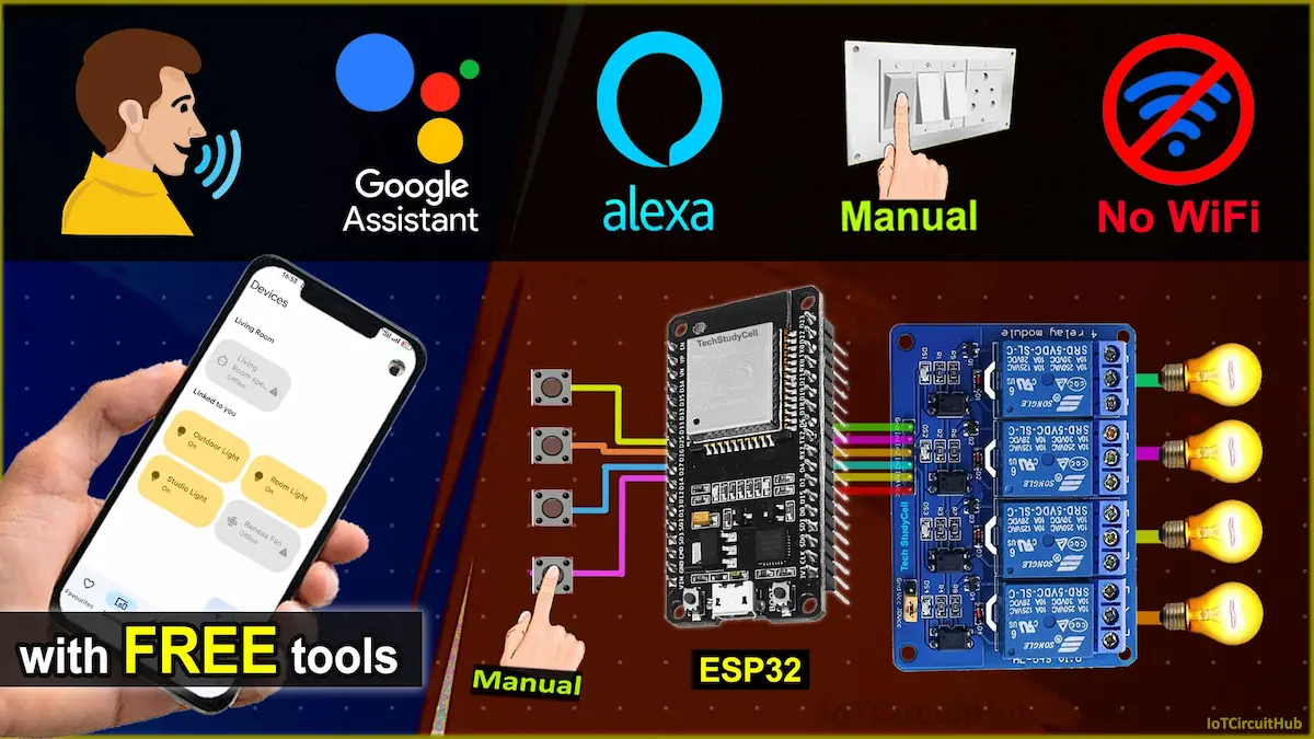
In this Internet of Things project, I have explained how to make an IoT-based ESP32 project using Google Assistant, Amazon Alexa, and Sinric to control relays with voice commands and manual switches.

And you don’t need any Google Nest or Amazon Echo Dot devices for this voice control home automation project.

I have used the FREE plan of the Sinric Pro IoT platform for this ESP32 home automation project.
Table of Contents
Required Components for ESP32 Project:

- ESP32 DevKIT V1 Amazon
- 4-channel 5V SPDT Relay Module Amazon
- Manual Switches or Pushbuttons Amazon
- Amazon Echo Dot (optional) Amazon
- Google Nest Mini (optional)
Circuit of the ESP32 Home Automation

The circuit is straightforward, I have used D23, D22, D21 & D19 GPIO to control the 4-channel relay module.
The GPIO D13, D12, D14 & D27 are connected with switches to control the relay module manually.
I have used the INPUT_PULLUP function in Arduino IDE instead of using the pull-up resistors with each push button.
As per the source code, when the control pins of the relay module receive a LOW signal the relay will turn on and the relay will turn off for the HIGH signal in the control pin.
I have used a 5V 5Amp mobile charger to supply the circuit.
Please take proper safety precautions while connecting the AC appliances.
For the push-button, you can refer to the following circuit.

Tutorial video on ESP32 IoT Project
In the ESP32 IoT tutorial video, I covered the following topics.
- How to configure the Sinric Pro for ESP32.
- How to generate source code using Zero Code features of Sinric.
- Upload the Auto-generated code to ESP32.
- Circuit for connecting all the components with ESP32 relay.
- Add the device to the Google Home app.
- Add the device to the Amazon Alexa app.
Configure Sinric Pro for ESP32

For this ESP32 project, I have used the Sinric Pro Free account. First, you have to add devices to the Sinric Pro account.
I have already explained, how to set up and add devices to Sinric Pro in the following article.
PCB for the ESP32 project
You can also use the following PCB for this home automation project.
You can order any custom-designed PCBs from PCBWay at very reasonable prices.

PCBWay not only produces FR-4 and Aluminum boards but also advanced PCBs like Rogers, HDI, and Flexible and Rigid-Flex boards, at very affordable prices.
For the online instant quote page please visit – pcbway.com/orderonline
You can also explore different PCB projects from their Open-source community pcbway.com/project/.
For more details please visit the following articles.
Why PCBway
Program ESP32 with Arduino IDE
In the Tutorial video, I have explained all the steps to program the ESP32 using Arduino IDE.
- Update the Preferences –> Additional boards Manager URLs: https://dl.espressif.com/dl/package_esp32_index.json, http://arduino.esp8266.com/stable/package_esp8266com_index.json
- Then install the ESP32 board from the Board Manager or Click Here to download the ESP32 board.
- Download the required libraries from the following links:
- Sinric Pro by Boris Jaeger (Download Sinric Pro examples for ESP8266 & ESP32)
- WebSockets by Markus Sattler (Minimum Version 2.3.5)
- ArduinoJson by Benoit Blanchon (Minimum Version 6.12.0)
Click Here to visit the GitHub page of Sinric Pro for more details.
In this project, I have used the “Zero Code” features of the Sinric Pro to generate the source code. Please refer to the related tutorial video for the steps.

Code for the ESP32 Relay module
#ifdef ENABLE_DEBUG
  #define DEBUG_ESP_PORT Serial
  #define NODEBUG_WEBSOCKETS
  #define NDEBUG
#endif

#include <Arduino.h>
#if defined(ESP8266)
  #include <ESP8266WiFi.h>
#elif defined(ESP32) || defined(ARDUINO_ARCH_RP2040)
  #include <WiFi.h>
#endif

#include "SinricPro.h"
#include "SinricProSwitch.h"
#include <map>

#define WIFI_SSID         ""
#define WIFI_PASS         ""
#define APP_KEY           "497d54da-bcfe-4615-ba8b-373471c1XXXX"
#define APP_SECRET        "7728ee8f-6d4d-41a5-985b-75a6500e94fa-e5091d67-373a-48f9-8525-5573eXXXXXX"

// comment the following line if you use a toggle switches instead of tactile buttons

#define BAUD_RATE   115200

#define DEBOUNCE_TIME 250

#define RELAYPIN_1 23
#define RELAYPIN_2 22
#define RELAYPIN_3 21

typedef struct {      // struct for the std::map below
  int relayPIN;
  int flipSwitchPIN;
  bool activeLow;
} deviceConfig_t;

// this is the main configuration
// please put in your deviceId, the PIN for Relay and PIN for flipSwitch
// this can be up to N devices...depending on how much pin's available on your device ;)
// right now we have 4 devicesIds going to 4 relays and 4 flip switches to switch the relay manually
std::map<String, deviceConfig_t> devices = {
    //{deviceId, {relayPIN,  flipSwitchPIN, activeLow}}
    {"65c43317ccc93539a13550ac", {  23, 13, true }},
    {"65c432eab0a460b25b3ecb54", {  22, 12, true }},
    {"65c4334bb0a460b25b3ecbba", {  21, 14, true }},

};

typedef struct {      // struct for the std::map below
  String deviceId;
  bool lastFlipSwitchState;
  unsigned long lastFlipSwitchChange;
  bool activeLow;
} flipSwitchConfig_t;

std::map<int, flipSwitchConfig_t> flipSwitches;    // this map is used to map flipSwitch PINs to deviceId and handling debounce and last flipSwitch state checks
                                                  // it will be setup in "setupFlipSwitches" function, using informations from devices map

void setupRelays() {
  for (auto &device : devices) {           // for each device (relay, flipSwitch combination)
    int relayPIN = device.second.relayPIN; // get the relay pin
    pinMode(relayPIN, OUTPUT);             // set relay pin to OUTPUT
    digitalWrite(relayPIN, HIGH);
  }
}

void setupFlipSwitches() {
  for (auto &device : devices)  {                     // for each device (relay / flipSwitch combination)
    flipSwitchConfig_t flipSwitchConfig;              // create a new flipSwitch configuration

    flipSwitchConfig.deviceId = device.first;         // set the deviceId
    flipSwitchConfig.lastFlipSwitchChange = 0;        // set debounce time
    flipSwitchConfig.lastFlipSwitchState = false;     // set lastFlipSwitchState to false (LOW)
    int flipSwitchPIN = device.second.flipSwitchPIN;  // get the flipSwitchPIN
    bool activeLow = device.second.activeLow;         // set the activeLow
    flipSwitchConfig.activeLow = activeLow;
    flipSwitches[flipSwitchPIN] = flipSwitchConfig;   // save the flipSwitch config to flipSwitches map

    if(activeLow) {
      pinMode(flipSwitchPIN, INPUT_PULLUP);           // set the flipSwitch pin to INPUT_PULLUP
    }
    else {
      pinMode(flipSwitchPIN, INPUT);                  // set the flipSwitch pin to INPUT
    }
  }
}

bool onPowerState(String deviceId, bool &state) {
  Serial.printf("%s: %s\r\n", deviceId.c_str(), !state ? "on" : "off");
  int relayPIN = devices[deviceId].relayPIN; // get the relay pin for corresponding device
  digitalWrite(relayPIN, !state);             // set the new relay state
  return true;
}

void handleFlipSwitches() {
  unsigned long actualMillis = millis();                                          // get actual millis
  for (auto &flipSwitch : flipSwitches) {                                         // for each flipSwitch in flipSwitches map
    unsigned long lastFlipSwitchChange = flipSwitch.second.lastFlipSwitchChange;  // get the timestamp when flipSwitch was pressed last time (used to debounce / limit events)

    if (actualMillis - lastFlipSwitchChange > DEBOUNCE_TIME) {                    // if time is > debounce time...

      int flipSwitchPIN = flipSwitch.first;                                       // get the flipSwitch pin from configuration
      bool lastFlipSwitchState = flipSwitch.second.lastFlipSwitchState;           // get the lastFlipSwitchState
      bool activeLow = flipSwitch.second.activeLow;
      bool flipSwitchState = digitalRead(flipSwitchPIN);                          // read the current flipSwitch state
      if(activeLow) flipSwitchState = !flipSwitchState;

      if (flipSwitchState != lastFlipSwitchState) {                               // if the flipSwitchState has changed...
#ifdef TACTILE_BUTTON
        if (flipSwitchState) {                                                    // if the tactile button is pressed
#endif
          flipSwitch.second.lastFlipSwitchChange = actualMillis;                  // update lastFlipSwitchChange time
          String deviceId = flipSwitch.second.deviceId;                           // get the deviceId from config
          int relayPIN = devices[deviceId].relayPIN;                              // get the relayPIN from config
          bool newRelayState = !digitalRead(relayPIN);                            // set the new relay State
          digitalWrite(relayPIN, newRelayState);                                  // set the trelay to the new state

          SinricProSwitch &mySwitch = SinricPro[deviceId];                        // get Switch device from SinricPro
          mySwitch.sendPowerStateEvent(newRelayState);                            // send the event
#ifdef TACTILE_BUTTON
        }
#endif
        flipSwitch.second.lastFlipSwitchState = flipSwitchState;                  // update lastFlipSwitchState
      }
    }
  }
}

void setupWiFi() {
  Serial.printf("\r\n[Wifi]: Connecting");

  #if defined(ESP8266)
    WiFi.setSleepMode(WIFI_NONE_SLEEP);
    WiFi.setAutoReconnect(true);
  #elif defined(ESP32)
    WiFi.setSleep(false);
    WiFi.setAutoReconnect(true);
  #endif

  WiFi.begin(WIFI_SSID, WIFI_PASS);

  while (WiFi.status() != WL_CONNECTED)
  {
    Serial.printf(".");
    delay(250);
  }

  Serial.printf("connected!\r\n[WiFi]: IP-Address is %s\r\n", WiFi.localIP().toString().c_str());
}

void setupSinricPro() {
  for (auto &device : devices) {
    const char *deviceId = device.first.c_str();
    SinricProSwitch &mySwitch = SinricPro[deviceId];
    mySwitch.onPowerState(onPowerState);
  }


  SinricPro.begin(APP_KEY, APP_SECRET);
}

void setup() {
  Serial.begin(BAUD_RATE);
  setupRelays();
  setupFlipSwitches();
  setupWiFi();
  setupSinricPro();
}

void loop() {
  SinricPro.handle();
  handleFlipSwitches();
}
Enter the APP KEY and APP SECRET with the Wi-Fi name and Wi-Fi password in the code.
You can get the APP KEY and APP SECRET under the Credentials menu in Sinric Pro
#define WIFI_SSID         "YOUR-WIFI-NAME"
#define WIFI_PASS         "YOUR-WIFI-PASSWORD"
#define APP_KEY           "YOUR-APP-KEY"
#define APP_SECRET        "YOUR-APP-SECRET"
Also, enter the device ID in the code. You will find the Device ID from the Devices menu.
//{deviceId, {relayPIN,  flipSwitchPIN, activeLow}}
    {"65c43317ccc93539a13550ac", {  23, 13, true }},
    {"65c432eab0a460b25b3ecb54", {  22, 12, true }},
    {"65c4334bb0a460b25b3ecbba", {  21, 14, true }},
**A unique ID is assigned When you add a device in Sinric Pro. If 3 devices are created, there will be 3 distinct device IDs assigned to each device.
Here, I have used the ZeroCode features of the Sinric Pro to generate the source code, so all related details like App Key, App Secret, WiFi credentials, and Device IDs were auto-filled by SInric Pro.
After uploading the code to ESP32, please refer to the following articles for connecting the Sinric Pro Account with Amazon Alexa and Google Home App.
After doing all these steps, now you control the appliances with Google Assistant and Alexa.
ESP32 control Relays with Alexa App


If the ESP32 is connected with Wi-Fi, then you can ask Alexa, to turn on the light [“Alexa, Turn ON Room Light“]. Thus, you can control the appliances like light, fan, etc with voice commands using Amazon Alexa App, and also monitor the current status of the switches from anywhere in the world from the Alexa App.
ESP32 control Relays with Google Assistant

You can also ask Google Assistant, to control the light [“Hey Google, Turn ON the Room Light“]. Thus, you can control appliances like lights, fans, etc with voice commands using Google Assistant, and also monitor the real-time feedback and control the relays from anywhere in the world from the Google Home App.
Control relays manually with Switches

You can always control the appliances manually with switches or push buttons and monitor the real-time status in the Google Home and Alexa Apps.
I hope you like this Smart house IoT project idea with the Espressif ESP32.
Click Here for more such ESP32 projects.
Please do share your feedback on this IoT project. Thank you for your time.


