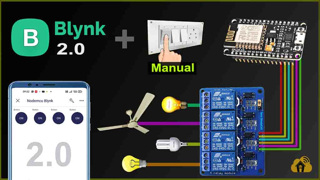
In this internet of things project, I have explained how to make home automation using NodeMCU and Blynk 2.0 with real-time feedback. With this NodeMCU ESP8266 project, you can control 4 home appliances with the manual switches and Blynk IoT app from anywhere in the world through the internet. You can also control the appliances from the Blynk cloud web dashboard.

I have used all the FREE tools for this NodeMCU home automation project using Blynk IoT.
So if you follow all the steps, you can easily make this Smart Home System with NodeMCU and Blynk app.
Table of Contents
Circuit of the Blynk NodeMCU Home Automation projects

The circuit is very simple, I have used D1, D2, D5 & D6 GPIO pins to control the 4-channel relay module.
And the GPIO SD3, D3, D7 & RX are connected with the switches to control the relay module manually.
I have used the INPUT_PULLUP function in Arduino IDE instead of using the pull-up resistors with each switch.
As per the source code, when the control pins of the relay module receive the LOW signal the respective relay will turn on and the relay will turn off for the HIGH signal in the control pin.
**The Boot will fail if SD3 and D3 are grounded during the Boot process. So manual switch-S1 and switch-S2 must be OFF during NodeMCU Boot.
Now, if you want to use pushbuttons then just connect the pushbuttons across the GPIO pins and GND pin instead of switches.
I have used a 5V 5Amp power supply to supply the NodeMCU and relay module.
Required Components for the NodeMCU projects

- NodeMCU
- 4-channel 5V SPDT Relay Module
- Pushbuttons or Switches
Tutorial video on Blynk ESP8266 Home Automation
In this Blynk 2.0 tutorial video, I have covered the following steps in detail.
- Create an account at Blynk IoT Cloud.
- Create a template for ESP8266 in Blynk IoT Cloud.
- Set up Blynk Cloud Web Dashboard.
- Install and set up Blynk IoT App in mobile.
- Program the NodeMCU with Arduino IDE
- Update the Wi-Fi credentials to ESP8266 through OTA.
- Control relays with Blynk IoT app from mobile.
Recently I have done some modifications in the code to control the relay without Wi-Fi.
Latest video on Blynk NodeMCU Home Automation.
NodeMCU control Relays with Blynk IoT App

If the NodeMCU is connected to Wi-Fi, then you can control the relay module with Blynk App. You can control, and monitor the real-time feedback of the relays from anywhere in the world from the Blynk App.
When the internet comes back, the NodeMCU will fetch the previous state of the switches from the Blynk IoT cloud server and accordingly turn on and off the relays.
Control Relays with Switches or Push Buttons

You can also manually control the appliances from the switches or pushbuttons. If the NodeMCU is connected to Wi-Fi then it will send real-time feedback to the Blynk IoT server.
Blynk IoT Cloud setup
Please refer to the following article for the Blynk IoT Cloud account setup.
Getting started with New Blynk 2.0 IoT platform
Program NodeMCU with Arduino IDE
In the Tutorial video, I explained all the steps to program the NodeMCU using Arduino IDE.
- Update the Preferences –> Aditional boards Manager URLs: https://dl.espressif.com/dl/package_esp32_index.json, http://arduino.esp8266.com/stable/package_esp8266com_index.json
- Then install the ESP8266 board from the Board manager or Click Here to download the ESP8266 board.
- Install all the required libraries in Arduino IDE:
- Install the Blynk library from Include Library or Click Here to download.

Go to Sketch -> Include Libraries -> Manage Libraries in Arduino IDE.
When you try to install the Blynk library, it may ask you to install all the dependencies. Then Click on Install All.
Code for Blynk IoT Cloud ESP8266 home automation

After downloading the code, you will get total 10 files. ( 1 .ino & 9 .h files). You have to keep all these files in the same folder.
Then open the .ino file in Arduino IDE, select the NodeMCU 1.0 board then compile the code. If you have downloaded all the required libraries then you should not get any errors.
In code, you have to update only the BLYNK_TEMPLATE_ID & BLYNK_DEVICE_NAME as shown in the video. You don’t have to enter the W-Fi credentials in the code.

Now upload the code to NodeMCU.
In the tutorial video, I have explained, how to update Wi-Fi credentials from the Blynk IoT app.
PCB for the NodeMCU Smart Home Project

If you want, you can also use this PCB to make the circuit compact and give the project a professional look.
Components Required for PCB
- Relays 5v (SPDT) (4 no)
- BC547 Transistors (4 no)
- PC817 Optocuplors (4 no)
- 510-ohm 0.25-watt Resistor (4 no) (R1-R4)
- 1k 0.25-watt Resistors (5 no) (R5-R9)
- 1N4007 Diodes (5 no) (D1-D5)
- LED 5-mm (5 no)
- Push Buttons (4 no)
- Terminal Connectors
- 5V 2A DC supply
Connect Home Appliances with Relays

Connect the home appliances with the relay module as per the circuit diagram.
Please take proper safety precautions, while working with high voltage.
Now, turn on the 5V DC supply and 110V/220V AC supply.
Finally, the ESP32 Smart Home System is ready


I hope you like this Smart house IoT projects idea with the new Blynk 2.0 IoT Cloud and NodeMCU ESP8266.
Click Here for more such ESP8266 projects.
Please do share your feedback on this IoT project. Thank you for your time.


