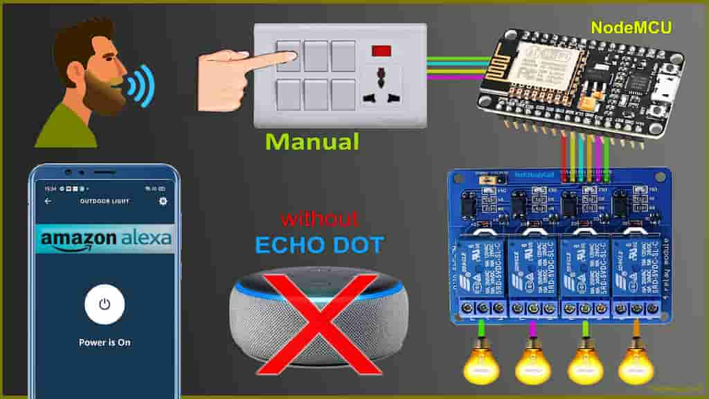
In this IoT project, I have explained how to make a NodeMCU Alexa home automation system with Sinric. With this NodeMCU ESP8266 project, you can control 4 home appliances from the Amazon Alexa App and manual switches. You can control the relay module from the manual switches if there is no internet available.
And you don’t need an Amazon Echo Dot devices for this voice control home automation project.
**This tutorial is outdated. Follow the new tutorial instead: [NEW] ESP8266 Home Automation with Alexa & Google Assistant.

With this IoT project, you can control & monitor the real-time feedback of the relays in the Alexa App from anywhere in the world. If the WiFi is available, the NodeMCU will automatically connect with the WiFi and the blue LED will turn on.
Table of Contents
Circuit of the NodeMCU Alexa Home Automation

The circuit is very simple, I have used D1, D2, D5 & D6 GPIO to control the 4-channel relay module.
And the GPIO SD3, D3, D7 & RX connected with manual switches to control the relay module manually.
I have used the INPUT_PULLUP function in Arduino IDE instead of using the pull-up resistors with each switch.
As per the source code, when the control pins of the relay module receive the LOW signal the respective relay will turn on and the relay will turn off for the HIGH signal in the control pin.
I have used a 5V 2Amp mobile charger to supply the circuit.
**The Boot will fail if SD3 and D3 are grounded during the Boot process. So manual switch-S1 and switch-S2 must be OFF during NodeMCU Boot.
Required Components for the NodeMCU projects

- NodeMCU
- 4-channel 5V SPDT Relay Module
- Manual Switches
- Amazon Echo Dot (optional)
Control Relays with Alexa App

If the NodeMCU is connected with WiFi, then you can control the relay module from Amazon Alexa App and manual switches. You can control the appliances like light, fan, etc with voice commands, and also monitor the current status of the switches from anywhere in the world from the Alexa App.

Control Relays without WiFi
If the WiFi not available, the blue LED on NodeMCU will turn OFF. Then you can control the relays manually only using switches.

The NodeMCU will check for the WiFi after every 3 seconds. When the internet comes back, the NodeMCU will automatically connect with the WiFi. ANd the blue LED will turn ON.
Tutorial video on NodeMCU Alexa Home Automation
In the tutorial video, I have covered the following steps in details.
- Control 4-channel relay module with Alexa and switches.
- Create an account and add devices in Sinric.com.
- Programming the NodeMCU with Arduino IDE
- Connect IoT devices & ESP8266 NodeMCU with Amazon Alexa App.
- Connect home appliances with the 4-channel relay module.
Create an Account in Sinric.com

First, visit Sinric.com. Then click in Resistor to create an account.

Then enter Name, Email Id and set a password for the Sinric account.
Then click on “Submit“.
Add Devices in Sinric account

After Login, you will get a API Key which will be required in the code.
Now, to add devices, click on “Add“.

Then, give a Device Name (Alexa will identify the device with this name).
Select the Device Type as “Switch“.
Then click on “Save“.

Thus you can add multiple devices in the Sinric dashboard.
Program NodeMCU with Arduino IDE
In the Tutorial video, I have explained all the steps to program the NodeMCU using Arduino IDE.
- Update the Preferences –> Aditional boards Manager URLs: https://dl.espressif.com/dl/package_esp32_index.json, http://arduino.esp8266.com/stable/package_esp8266com_index.json
- Then install the ESP8266 board from the Board manager or Click Here to download the ESP8266 board.
- Download the required libraries from the following links:
- arduinoWebSockets Library: Click Here
- AceButton Library: Click Here
- ArduinoJson Library: Click Here
**Please download the latest version of the libraries from the given links. Then install the libraries at Arduino IDE – Sketch – Include Library – Add Zip Library.
Code for NodeMCU ESP8266 Alexa controlled relay
#include <Arduino.h>
#include <ESP8266WiFi.h>
#include <ESP8266WiFiMulti.h>
#include <WebSocketsClient.h>
#include <ArduinoJson.h>
#include <StreamString.h>

#include <AceButton.h>
using namespace ace_button;
ESP8266WiFiMulti WiFiMulti;
WebSocketsClient webSocket;
WiFiClient client;

#define MyApiKey "---------------------" // TODO: Change to your sinric API Key. Your API Key is displayed on sinric.com dashboard
#define MySSID "------" // TODO: Change to your Wifi network SSID
#define MyWifiPassword "-------" // TODO: Change to your Wifi network password

#define HEARTBEAT_INTERVAL 300000 // 5 Minutes

uint64_t heartbeatTimestamp = 0;
bool isConnected = false;

String device_ID_1 = "------------------------";
String device_ID_2 = "------------------------";
String device_ID_3 = "------------------------";
String device_ID_4 = "------------------------";

// define the GPIO connected with Relays and switches

// Relays
#define RelayPin1 D1  //D1
#define RelayPin2 D2  //D2
#define RelayPin3 D5  //D5
#define RelayPin4 D6  //D6

// Switches
#define SwitchPin1 10  //SD3
#define SwitchPin2 D3   //D3
#define SwitchPin3 D7  //D7
#define SwitchPin4 3   //RX

//WiFi Status LED
#define wifiLed    D0   //D0


ButtonConfig config1;
AceButton button1(&config1);
ButtonConfig config2;
AceButton button2(&config2);
ButtonConfig config3;
AceButton button3(&config3);
ButtonConfig config4;
AceButton button4(&config4);


void handleEvent1(AceButton*, uint8_t, uint8_t);
void handleEvent2(AceButton*, uint8_t, uint8_t);
void handleEvent3(AceButton*, uint8_t, uint8_t);
void handleEvent4(AceButton*, uint8_t, uint8_t);

void setPowerStateOnServer(String deviceId, String value);

// deviceId is the ID assgined to your smart-home-device in sinric.com dashboard. Copy it from dashboard and paste it here

void turnOn(String deviceId) {
  if (deviceId == device_ID_1) // Device ID of 1st device
  {
    Serial.print("Turn on device id: ");
    Serial.println(deviceId);
    digitalWrite(RelayPin1, LOW);
  }
  if (deviceId == device_ID_2) // Device ID of 2nd device
  {
    Serial.print("Turn on device id: ");
    Serial.println(deviceId);
    digitalWrite(RelayPin2, LOW);
  }
  if (deviceId == device_ID_3) // Device ID of 3rd device
  {
    Serial.print("Turn on device id: ");
    Serial.println(deviceId);
    digitalWrite(RelayPin3, LOW);
  }
  if (deviceId == device_ID_4) // Device ID of 4th device
  {
    Serial.print("Turn on device id: ");
    Serial.println(deviceId);
    digitalWrite(RelayPin4, LOW);
  }
}

void turnOff(String deviceId) {
  if (deviceId == device_ID_1) // Device ID of 1st device
  {
    Serial.print("Turn off Device ID: ");
    Serial.println(deviceId);
    digitalWrite(RelayPin1, HIGH);
  }
  if (deviceId == device_ID_2) // Device ID of 2nd device
  {
    Serial.print("Turn off Device ID: ");
    Serial.println(deviceId);
    digitalWrite(RelayPin2, HIGH);
  }
  if (deviceId == device_ID_3) // Device ID of 3rd device
  {
    Serial.print("Turn off Device ID: ");
    Serial.println(deviceId);
    digitalWrite(RelayPin3, HIGH);
  }
  if (deviceId == device_ID_4) // Device ID of 4th device
  {
    Serial.print("Turn off Device ID: ");
    Serial.println(deviceId);
    digitalWrite(RelayPin4, HIGH);
  }
}

void webSocketEvent(WStype_t type, uint8_t * payload, size_t length) {
  switch (type) {
    case WStype_DISCONNECTED:
      isConnected = false;
      WiFiMulti.addAP(MySSID, MyWifiPassword);
      Serial.printf("[WSc] Webservice disconnected from sinric.com!\n");
      break;
    case WStype_CONNECTED: {
        isConnected = true;
        Serial.printf("[WSc] Service connected to sinric.com at url: %s\n", payload);
        Serial.printf("Waiting for commands from sinric.com ...\n");
      }
      break;
      case WStype_TEXT: {
        Serial.printf("[WSc] get text: %s\n", payload);

        #if ARDUINOJSON_VERSION_MAJOR == 5
                DynamicJsonBuffer jsonBuffer;
                JsonObject& json = jsonBuffer.parseObject((char*)payload);
        #endif
        #if ARDUINOJSON_VERSION_MAJOR == 6
                DynamicJsonDocument json(1024);
                deserializeJson(json, (char*) payload);
        #endif
        String deviceId = json ["deviceId"];
        String action = json ["action"];

        if (action == "setPowerState") { // Switch or Light
          String value = json ["value"];
          if (value == "ON") {
            turnOn(deviceId);
          } else {
            turnOff(deviceId);
          }
        }
        else if (action == "test") {
          Serial.println("[WSc] received test command from sinric.com");
        }
      }
      break;
    case WStype_BIN:
      Serial.printf("[WSc] get binary length: %u\n", length);
      break;
  }
}

void setup() {
  Serial.begin(9600);

  WiFiMulti.addAP(MySSID, MyWifiPassword);
  Serial.println();
  Serial.print("Connecting to Wifi: ");
  Serial.println(MySSID);

  // Waiting for Wifi connect
  if (WiFiMulti.run() != WL_CONNECTED) {
    delay(500);
    Serial.print("Connecting...");
  }
  if (WiFiMulti.run() == WL_CONNECTED) {
    Serial.println("");
    Serial.print("WiFi connected. ");
    Serial.print("IP address: ");
    Serial.println(WiFi.localIP());
  }

  pinMode(SwitchPin1, INPUT_PULLUP);
  pinMode(SwitchPin2, INPUT_PULLUP);
  pinMode(SwitchPin3, INPUT_PULLUP);
  pinMode(SwitchPin4, INPUT_PULLUP);

  pinMode(RelayPin1, OUTPUT);
  pinMode(RelayPin2, OUTPUT);
  pinMode(RelayPin3, OUTPUT);
  pinMode(RelayPin4, OUTPUT);

  pinMode(wifiLed, OUTPUT);

  //During Starting all Relays should TURN OFF
  digitalWrite(RelayPin1, HIGH);
  digitalWrite(RelayPin2, HIGH);
  digitalWrite(RelayPin3, HIGH);
  digitalWrite(RelayPin4, HIGH);

  //During Starting WiFi LED should TURN OFF
  digitalWrite(wifiLed, HIGH);

  config1.setEventHandler(button1Handler);
  config2.setEventHandler(button2Handler);
  config3.setEventHandler(button3Handler);
  config4.setEventHandler(button4Handler);

  button1.init(SwitchPin1);
  button2.init(SwitchPin2);
  button3.init(SwitchPin3);
  button4.init(SwitchPin4);

  // server address, port and URL
  webSocket.begin("iot.sinric.com", 80, "/");

  // event handler
  webSocket.onEvent(webSocketEvent);
  webSocket.setAuthorization("apikey", MyApiKey);

  // try again every 5000ms if connection has failed
  webSocket.setReconnectInterval(5000);   // If you see 'class WebSocketsClient' has no member named 'setReconnectInterval' error update arduinoWebSockets
}

void loop() {

  if (WiFiMulti.run() != WL_CONNECTED)
  {
    //  Serial.println("Not Connected");
    digitalWrite(wifiLed, HIGH);
  }
  else
  {
    //Serial.println(" Connected");
    digitalWrite(wifiLed, LOW);
    webSocket.loop();
  }

  button1.check();
  button2.check();
  button3.check();
  button4.check();

  if (isConnected) {
    uint64_t now = millis();

    // Send heartbeat in order to avoid disconnections during ISP resetting IPs over night. Thanks @MacSass
    if ((now - heartbeatTimestamp) > HEARTBEAT_INTERVAL) {
      heartbeatTimestamp = now;
      webSocket.sendTXT("H");
    }
  }
}

void setPowerStateOnServer(String deviceId, String value) {
  #if ARDUINOJSON_VERSION_MAJOR == 5
    DynamicJsonBuffer jsonBuffer;
    JsonObject& root = jsonBuffer.createObject();
  #endif
  #if ARDUINOJSON_VERSION_MAJOR == 6
    DynamicJsonDocument root(1024);
  #endif

    root["deviceId"] = deviceId;
    root["action"] = "setPowerState";
    root["value"] = value;
    StreamString databuf;
  #if ARDUINOJSON_VERSION_MAJOR == 5
    root.printTo(databuf);
  #endif
  #if ARDUINOJSON_VERSION_MAJOR == 6
    serializeJson(root, databuf);
  #endif
  webSocket.sendTXT(databuf);
}

void button1Handler(AceButton* button, uint8_t eventType, uint8_t buttonState) {
  Serial.println("EVENT1");
  switch (eventType) {
    case AceButton::kEventPressed:
      Serial.println("kEventPressed");
      setPowerStateOnServer(device_ID_1, "ON");
      digitalWrite(RelayPin1, LOW);
      break;
    case AceButton::kEventReleased:
      Serial.println("kEventReleased");
      setPowerStateOnServer(device_ID_1, "OFF");
      digitalWrite(RelayPin1, HIGH);
      break;
  }
}

void button2Handler(AceButton* button, uint8_t eventType, uint8_t buttonState) {
  Serial.println("EVENT2");
  switch (eventType) {
    case AceButton::kEventPressed:
      Serial.println("kEventPressed");
      setPowerStateOnServer(device_ID_2, "ON");
      digitalWrite(RelayPin2, LOW);
      break;
    case AceButton::kEventReleased:
      Serial.println("kEventReleased");
      setPowerStateOnServer(device_ID_2, "OFF");
      digitalWrite(RelayPin2, HIGH);
      break;
  }
}

void button3Handler(AceButton* button, uint8_t eventType, uint8_t buttonState) {
  Serial.println("EVENT3");
  switch (eventType) {
    case AceButton::kEventPressed:
      Serial.println("kEventPressed");
      setPowerStateOnServer(device_ID_3, "ON");
      digitalWrite(RelayPin3, LOW);
      break;
    case AceButton::kEventReleased:
      Serial.println("kEventReleased");
      setPowerStateOnServer(device_ID_3, "OFF");
      digitalWrite(RelayPin3, HIGH);
      break;
  }
}

void button4Handler(AceButton* button, uint8_t eventType, uint8_t buttonState) {
  Serial.println("EVENT4");
  switch (eventType) {
    case AceButton::kEventPressed:
      Serial.println("kEventPressed");
      setPowerStateOnServer(device_ID_4, "ON");
      digitalWrite(RelayPin4, LOW);
      break;
    case AceButton::kEventReleased:
      Serial.println("kEventReleased");
      setPowerStateOnServer(device_ID_4, "OFF");
      digitalWrite(RelayPin4, HIGH);
      break;
  }
}
Enter the following WiFi credential and the Sinric API Key in the code:
#define MyApiKey "----------------"
#define MySSID "--------"
#define MyWifiPassword "---------" - API Key from the Sinric at “MyApiKey“
- WiFi Name at “MySSID“
- WiFi Password at “MyWifiPassword”
String device_ID_1 = "------------------------";
String device_ID_2 = "------------------------";
String device_ID_3 = "------------------------";
String device_ID_4 = "------------------------";
Enter Device IDs for 4 devices from the Sinric dashboard.
Then Goto Tools and select the board as “NodeMCU 1.0 (ESP-12E Module)” and the proper PORT in Arduino IDE.
Then click on the upload button to program the NodeMCU board.
Configure the Amazon Alexa App

After uploading the code to NodeMCU, you have to configure the Amazon Alexa App.
During this process, the NodeMCU should be connected with the WiFi.
- Download the Amazon Alexa App from Google Play Store or App Store
- Goto More, then select “Skills & Games“
- Search for Sinric and tap on “Sinric“.
- Tap on “ENABLE TO USE“

- Log in with the Sinric account credentials.
- Goto Alexa and tap on “DISCOVER DEVICES“.
- It takes a minute to add devices. During this time the ESP32 should be connected with WiFi.
- Tap on “Devices“, then tap on “Switch” to see all the devices.
Now, you can control the connected home appliances with Alexa.
PCB for the Alexa ESP8266 Projects

To give the project a professional look and make the circuit compact, I have designed a PCB for this ESP8266 NodeMCU home automation project.
Solder the Components on PCB

Solder all the components as mentioned on the PCB.
Components Required for PCB
- Relays 5v (SPDT) (4 no)
- BC547 Transistors (4 no)
- PC817 Optocuplors (4 no)
- 510-ohm 0.25-watt Resistor (4 no) (R1-R4)
- 1k 0.25-watt Resistors (5 no) (R5-R9)
- 1N4007 Diodes (5 no) (D1-D5)
- LED 5-mm (5 no)
- Push Buttons (4 no)
- Terminal Connectors
- 5V DC supply
Connect Home Appliances with Relays

Connect the home appliances with the relay module as per the circuit diagram.
Please take proper safety precaution, while working with high voltage.
Now, turn on the 5V DC supply and 110V/220V AC supply.
Finally, the NodeMCU Smart Home System is ready

Now, you can control all 4 home appliances from the Alexa app with voice commands and also monitor real-time feedback from anywhere in the world.

I hope you like this Smart house IoT projects idea with the NodeMCU and Amazon Alexa app.
Click Here for more such ESP8266 projects.
Please do share your feedback on this IoT project. Thank you for your time.


