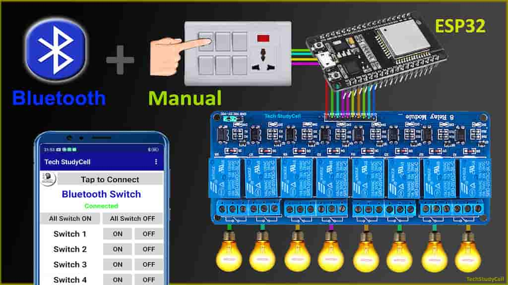
In this ESP32 project, I have explained how to make the ESP32 Bluetooth home automation system with manual switches to control an 8-channel relay module. You don’t need any WiFi, just connect the Bluetooth app with ESP32, and control the appliances from mobile. You can also turn ON and turn OFF the home appliances from switches or push buttons.

In this article, I have explained all the steps to make this smart home system using ESP32 and relay module.
Table of Contents
Circuit of the ESP32 Bluetooth Home Automation

I have used D23, D22, D21, D19, D18, D5, D25 & D26 GPIO to control the 8 relays.
And the GPIO D13, D12, D14, D27, D33, D32, D15 & D4 connected with manual switches to control the relay module manually.
You can also connect push buttons across the GPIOs and GND pin instead of switches.
I have used the INPUT_PULLUP function in Arduino IDE instead of using the pull-up resistors with each switch.
As per the source code, when the control pins of the relay module receive the LOW signal the respective relay will turn on and the relay will turn off for the HIGH signal in the control pin.
I have used a 5V 2Amp mobile charger to supply the circuit.
Required Components for the ESP32 projects

- ESP32 DEV KIT V1
- 8-channel 5V SPDT Relay Module
- Manual Switches or Push Buttons
Tutorial video on ESP32 Bluetooth project
In the tutorial video, I have explained all the steps to make this smart home system. Please watch the complete video for a better understanding.
Bluetooth App for ESP32 project

To control the ESP32 with Bluetooth, I have designed a Bluetooth App in MIT App Inventor.
Download the Bluetooth Switch App and install it. I have not submitted the App to Google Play Store. So you may get an alert while installing the App.
You can easily connect the Bluetooth App with ESP32 and control the appliance with Bluetooth.

When you press any buttons in the app, it will send the respective charecter through Bluetooth.
ESP32 will read the character, and turn ON and turn OFF the relays accordingly.
Program ESP32 with Arduino IDE
In the Tutorial video, I have explained all the steps to program the ESP32 DEV KIT V1 using Arduino IDE.
- Update the Preferences –> Aditional boards Manager URLs: https://dl.espressif.com/dl/package_esp32_index.json, http://arduino.esp8266.com/stable/package_esp8266com_index.json
- Then install the ESP32 board from the Board manager or Click Here to download the ESP32 board.
- Download the required libraries from the following links:
- BluetoothSerial Library: Click Here
- AceButton Library: Click Here
**Please download the latest version of the libraries from the given links. Then install the libraries at Arduino IDE – Sketch – Include Library – Add Zip Library.
Code for ESP32 Bluetooth controlled Relays
#include "BluetoothSerial.h"
#include <AceButton.h>
using namespace ace_button;

#if !defined(CONFIG_BT_ENABLED) || !defined(CONFIG_BLUEDROID_ENABLED)
#error Bluetooth is not enabled! Please run
`make menuconfig` to and enable it
#endif

BluetoothSerial SerialBT;

// define the GPIO connected with Relays and switches
#define RelayPin1 23  //D23
#define RelayPin2 22  //D22
#define RelayPin3 21  //D21
#define RelayPin4 19  //D19
#define RelayPin5 18  //D18
#define RelayPin6 5   //D5
#define RelayPin7 25  //D25
#define RelayPin8 26  //D26

#define SwitchPin1 13  //D13
#define SwitchPin2 12  //D12
#define SwitchPin3 14  //D14
#define SwitchPin4 27  //D27
#define SwitchPin5 33  //D33
#define SwitchPin6 32  //D32
#define SwitchPin7 15  //D15
#define SwitchPin8 4   //D4

int toggleState_1 = 1; //Define integer to remember the toggle state for relay 1
int toggleState_2 = 1; //Define integer to remember the toggle state for relay 2
int toggleState_3 = 1; //Define integer to remember the toggle state for relay 3
int toggleState_4 = 1; //Define integer to remember the toggle state for relay 4
int toggleState_5 = 1; //Define integer to remember the toggle state for relay 5
int toggleState_6 = 1; //Define integer to remember the toggle state for relay 6
int toggleState_7 = 1; //Define integer to remember the toggle state for relay 7
int toggleState_8 = 1; //Define integer to remember the toggle state for relay 8

char bt_data; // variable for storing bluetooth data

ButtonConfig config1;
AceButton button1(&config1);
ButtonConfig config2;
AceButton button2(&config2);
ButtonConfig config3;
AceButton button3(&config3);
ButtonConfig config4;
AceButton button4(&config4);
ButtonConfig config5;
AceButton button5(&config5);
ButtonConfig config6;
AceButton button6(&config6);
ButtonConfig config7;
AceButton button7(&config7);
ButtonConfig config8;
AceButton button8(&config8);


void handleEvent1(AceButton*, uint8_t, uint8_t);
void handleEvent2(AceButton*, uint8_t, uint8_t);
void handleEvent3(AceButton*, uint8_t, uint8_t);
void handleEvent4(AceButton*, uint8_t, uint8_t);
void handleEvent5(AceButton*, uint8_t, uint8_t);
void handleEvent6(AceButton*, uint8_t, uint8_t);
void handleEvent7(AceButton*, uint8_t, uint8_t);
void handleEvent8(AceButton*, uint8_t, uint8_t);

void all_Switch_ON(){
  digitalWrite(RelayPin1, LOW); toggleState_1 = 0; delay(100);
  digitalWrite(RelayPin2, LOW); toggleState_2 = 0; delay(100);
  digitalWrite(RelayPin3, LOW); toggleState_3 = 0; delay(100);
  digitalWrite(RelayPin4, LOW); toggleState_4 = 0; delay(100);
  digitalWrite(RelayPin5, LOW); toggleState_5 = 0; delay(100);
  digitalWrite(RelayPin6, LOW); toggleState_6 = 0; delay(100);
  digitalWrite(RelayPin7, LOW); toggleState_7 = 0; delay(100);
  digitalWrite(RelayPin8, LOW); toggleState_8 = 0; delay(100);
}

void all_Switch_OFF(){
  digitalWrite(RelayPin1, HIGH); toggleState_1 = 1; delay(100);
  digitalWrite(RelayPin2, HIGH); toggleState_2 = 1; delay(100);
  digitalWrite(RelayPin3, HIGH); toggleState_3 = 1; delay(100);
  digitalWrite(RelayPin4, HIGH); toggleState_4 = 1; delay(100);
  digitalWrite(RelayPin5, HIGH); toggleState_5 = 1; delay(100);
  digitalWrite(RelayPin6, HIGH); toggleState_6 = 1; delay(100);
  digitalWrite(RelayPin7, HIGH); toggleState_7 = 1; delay(100);
  digitalWrite(RelayPin8, HIGH); toggleState_8 = 1; delay(100);
}

void Bluetooth_handle()
{
  bt_data = SerialBT.read();
//  Serial.println(bt_data);
  delay(20);

  switch(bt_data)
      {
        case 'A': digitalWrite(RelayPin1, LOW);  toggleState_1 = 0; break; // if 'A' received Turn on Relay1
        case 'a': digitalWrite(RelayPin1, HIGH); toggleState_1 = 1; break; // if 'a' received Turn off Relay1
        case 'B': digitalWrite(RelayPin2, LOW);  toggleState_2 = 0; break; // if 'B' received Turn on Relay2
        case 'b': digitalWrite(RelayPin2, HIGH); toggleState_2 = 1; break; // if 'b' received Turn off Relay2
        case 'C': digitalWrite(RelayPin3, LOW);  toggleState_3 = 0; break; // if 'C' received Turn on Relay3
        case 'c': digitalWrite(RelayPin3, HIGH); toggleState_3 = 1; break; // if 'c' received Turn off Relay3
        case 'D': digitalWrite(RelayPin4, LOW);  toggleState_4 = 0; break; // if 'D' received Turn on Relay4
        case 'd': digitalWrite(RelayPin4, HIGH); toggleState_4 = 1; break; // if 'd' received Turn off Relay4
        case 'E': digitalWrite(RelayPin5, LOW);  toggleState_5 = 0; break; // if 'E' received Turn on Relay5
        case 'e': digitalWrite(RelayPin5, HIGH); toggleState_5 = 1; break; // if 'e' received Turn off Relay5
        case 'F': digitalWrite(RelayPin6, LOW);  toggleState_6 = 0; break; // if 'F' received Turn on Relay6
        case 'f': digitalWrite(RelayPin6, HIGH); toggleState_6 = 1; break; // if 'f' received Turn off Relay6
        case 'G': digitalWrite(RelayPin7, LOW);  toggleState_7 = 0; break; // if 'G' received Turn on Relay7
        case 'g': digitalWrite(RelayPin7, HIGH); toggleState_7 = 1; break; // if 'g' received Turn off Relay7
        case 'H': digitalWrite(RelayPin8, LOW);  toggleState_8 = 0; break; // if 'H' received Turn on Relay8
        case 'h': digitalWrite(RelayPin8, HIGH); toggleState_8 = 1; break; // if 'h' received Turn off Relay8
        case 'Z': all_Switch_ON(); break;  // if 'Z' received Turn on all Relays
        case 'z': all_Switch_OFF(); break; // if 'z' received Turn off all Relays
        default : break;
      }
}

void setup()
{
  Serial.begin(9600);

  btStart();  //Serial.println("Bluetooth On");

  SerialBT.begin("ESP32_BT"); //Bluetooth device name
  Serial.println("The device started, now you can pair it with bluetooth!");
  delay(5000);

  pinMode(RelayPin1, OUTPUT);
  pinMode(RelayPin2, OUTPUT);
  pinMode(RelayPin3, OUTPUT);
  pinMode(RelayPin4, OUTPUT);
  pinMode(RelayPin5, OUTPUT);
  pinMode(RelayPin6, OUTPUT);
  pinMode(RelayPin7, OUTPUT);
  pinMode(RelayPin8, OUTPUT);

//  pinMode(wifiLed, OUTPUT);

  pinMode(SwitchPin1, INPUT_PULLUP);
  pinMode(SwitchPin2, INPUT_PULLUP);
  pinMode(SwitchPin3, INPUT_PULLUP);
  pinMode(SwitchPin4, INPUT_PULLUP);
  pinMode(SwitchPin5, INPUT_PULLUP);
  pinMode(SwitchPin6, INPUT_PULLUP);
  pinMode(SwitchPin7, INPUT_PULLUP);
  pinMode(SwitchPin8, INPUT_PULLUP);

  //During Starting all Relays should TURN OFF
  digitalWrite(RelayPin1, toggleState_1);
  digitalWrite(RelayPin2, toggleState_2);
  digitalWrite(RelayPin3, toggleState_3);
  digitalWrite(RelayPin4, toggleState_4);
  digitalWrite(RelayPin5, toggleState_5);
  digitalWrite(RelayPin6, toggleState_6);
  digitalWrite(RelayPin7, toggleState_7);
  digitalWrite(RelayPin8, toggleState_8);

  config1.setEventHandler(button1Handler);
  config2.setEventHandler(button2Handler);
  config3.setEventHandler(button3Handler);
  config4.setEventHandler(button4Handler);
  config5.setEventHandler(button5Handler);
  config6.setEventHandler(button6Handler);
  config7.setEventHandler(button7Handler);
  config8.setEventHandler(button8Handler);

  button1.init(SwitchPin1);
  button2.init(SwitchPin2);
  button3.init(SwitchPin3);
  button4.init(SwitchPin4);
  button5.init(SwitchPin5);
  button6.init(SwitchPin6);
  button7.init(SwitchPin7);
  button8.init(SwitchPin8);

  delay(200);
}

void loop()
{
  if (SerialBT.available()){
   Bluetooth_handle();
 }

  button1.check();
  button2.check();
  button3.check();
  button4.check();
  button5.check();
  button6.check();
  button7.check();
  button8.check();
}

void button1Handler(AceButton* button, uint8_t eventType, uint8_t buttonState) {
  Serial.println("EVENT1");
  switch (eventType) {
    case AceButton::kEventPressed:
      Serial.println("kEventPressed");
      toggleState_1 = 0;
      digitalWrite(RelayPin1, LOW);
      break;
    case AceButton::kEventReleased:
      Serial.println("kEventReleased");
      toggleState_1 = 1;
      digitalWrite(RelayPin1, HIGH);
      break;
  }
}

void button2Handler(AceButton* button, uint8_t eventType, uint8_t buttonState) {
  Serial.println("EVENT2");
  switch (eventType) {
    case AceButton::kEventPressed:
      Serial.println("kEventPressed");
      toggleState_2 = 0;
      digitalWrite(RelayPin2, LOW);
      break;
    case AceButton::kEventReleased:
      Serial.println("kEventReleased");
      toggleState_2 = 1;
      digitalWrite(RelayPin2, HIGH);
      break;
  }
}

void button3Handler(AceButton* button, uint8_t eventType, uint8_t buttonState) {
  Serial.println("EVENT3");
  switch (eventType) {
    case AceButton::kEventPressed:
      Serial.println("kEventPressed");
      toggleState_3 = 0;
      digitalWrite(RelayPin3, LOW);
      break;
    case AceButton::kEventReleased:
      Serial.println("kEventReleased");
      toggleState_3 = 1;
      digitalWrite(RelayPin3, HIGH);
      break;
  }
}

void button4Handler(AceButton* button, uint8_t eventType, uint8_t buttonState) {
  Serial.println("EVENT4");
  switch (eventType) {
    case AceButton::kEventPressed:
      Serial.println("kEventPressed");
      toggleState_4 = 0;
      digitalWrite(RelayPin4, LOW);
      break;
    case AceButton::kEventReleased:
      Serial.println("kEventReleased");
      toggleState_4 = 1;
      digitalWrite(RelayPin4, HIGH);
      break;
  }
}

void button5Handler(AceButton* button, uint8_t eventType, uint8_t buttonState) {
  Serial.println("EVENT5");
  switch (eventType) {
    case AceButton::kEventPressed:
      Serial.println("kEventPressed");
      toggleState_5 = 0;
      digitalWrite(RelayPin5, LOW);
      break;
    case AceButton::kEventReleased:
      Serial.println("kEventReleased");
      toggleState_5 = 1;
      digitalWrite(RelayPin5, HIGH);
      break;
  }
}

void button6Handler(AceButton* button, uint8_t eventType, uint8_t buttonState) {
  Serial.println("EVENT6");
  switch (eventType) {
    case AceButton::kEventPressed:
      Serial.println("kEventPressed");
      toggleState_6 = 0;
      digitalWrite(RelayPin6, LOW);
      break;
    case AceButton::kEventReleased:
      Serial.println("kEventReleased");
      toggleState_6 = 1;
      digitalWrite(RelayPin6, HIGH);
      break;
  }
}

void button7Handler(AceButton* button, uint8_t eventType, uint8_t buttonState) {
  Serial.println("EVENT7");
  switch (eventType) {
    case AceButton::kEventPressed:
      Serial.println("kEventPressed");
      toggleState_7 = 0;
      digitalWrite(RelayPin7, LOW);
      break;
    case AceButton::kEventReleased:
      Serial.println("kEventReleased");
      toggleState_7 = 1;
      digitalWrite(RelayPin7, HIGH);
      break;
  }
}

void button8Handler(AceButton* button, uint8_t eventType, uint8_t buttonState) {
  Serial.println("EVENT8");
  switch (eventType) {
    case AceButton::kEventPressed:
      Serial.println("kEventPressed");
      toggleState_8 = 0;
      digitalWrite(RelayPin8, LOW);
      break;
    case AceButton::kEventReleased:
      Serial.println("kEventReleased");
      toggleState_8 = 1;
      digitalWrite(RelayPin8, HIGH);
      break;
  }
}
Then Goto Tools and select the board as “DOIT ESP32 DEVKIT V1” and the proper PORT in Arduino IDE.
Then click on the upload button to program the ESP32 board.
While uploading the code to ESP32, when you see the “Connecting….___” text, then press the BOOT button of the ESP32.
Connect Home Appliances with Relays

Connect the home appliances with the relay module as per the circuit diagram.
Please take proper safety precaution, while working with high voltage.
Now, turn on the 5V DC supply and 110V/220V AC supply.
Connect the ESP32 with Bluetooth

After uploading the code to ESP32, you have to connect the Bluetooth App with ESP32.
- Turn ON mobile Bluetooth and Pair the ESP32.
- Open the Bluetooth Switch App and tap on “Tap to Connect”.
- Select the “ESP32_BT” from the list.
- Now, you can control the relay from mobile with Bluetooth.
Controlling Relay with Bluetooth

After connecting the ESP32 with Bluetooth Switch App, you can easily turn ON and turn OFF the home appliances from smart phone.

You can also control the home appliances with manual switches or push buttons.
I hope you like this ESP32 home automation project.
Click Here for more such ESP32 projects.
Please do share your feedback on this IoT project. Thank you for your time.


