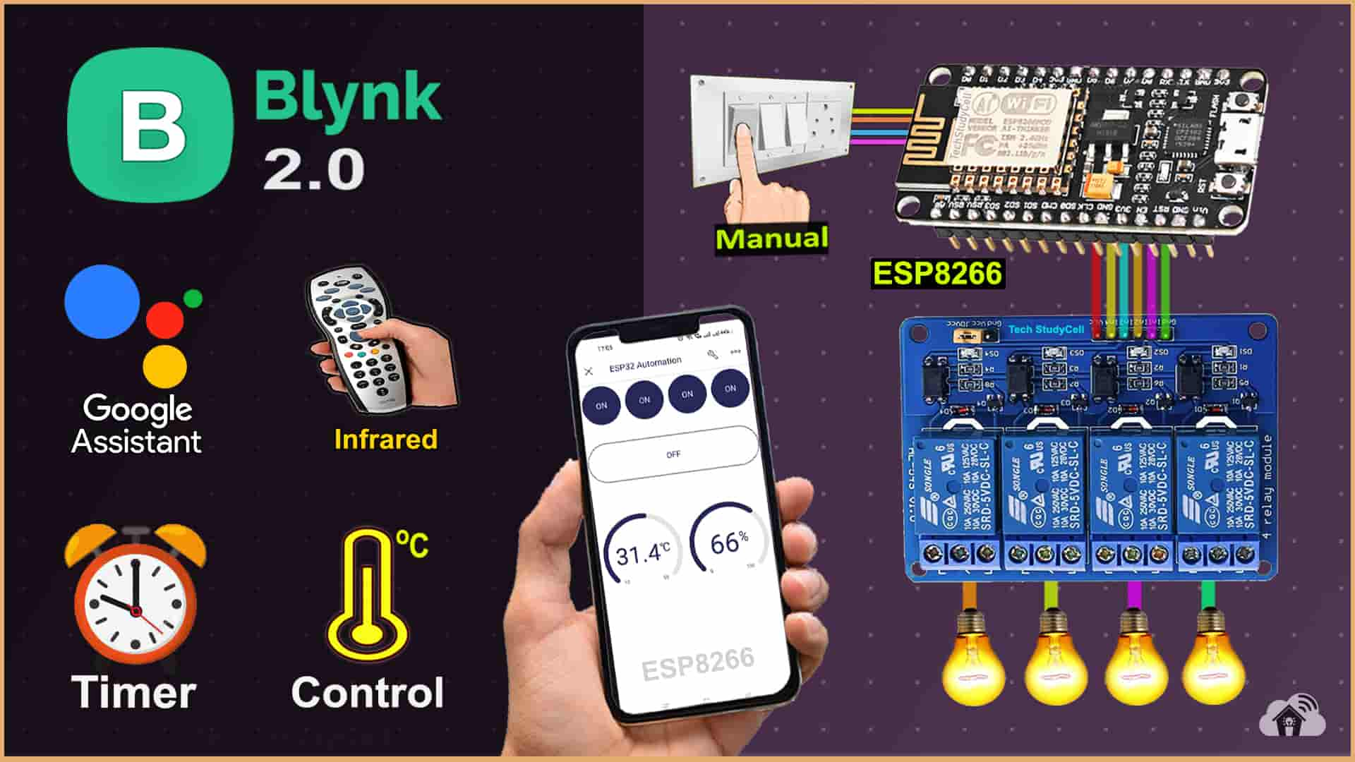
In this article, I have explained how to make an ESP8266 IoT project using NodeMCU and sensors with the New Blynk Automation.
With this IoT project, you can set the timer and control the relays automatically with sensor readings in the Blynk IoT app.

You can still control 4 relays with the IR remote and manual switches if there is no internet.
The NodeMCU will automatically connect with the Blynk cloud if the WiFi is available. Then you can control the relays from anywhere in the world through the internet and monitor the real-time feedback and sensor reading in the Blynk IoT App.
I have used all the FREE tools for this ESP8266 IoT Project project using the Blynk app.
So if you follow all the steps, you can easily make this home automation system with ESP8266 NodeMCU and Blynk IoT.
Table of Contents
Required Components for the ESP8266 IoT project

- ESP8266 NodeMCU.
- 4-channel 5V SPDT Relay Module Amazon
- DHT11 Sensor Amazon
- TSOP1838 IR Receiver (with metallic case) Amazon
- Switches or Pushbuttons Amazon
- Any IR Remote
Circuit of the IoT Project using ESP8266 NodeMCU

The circuit is very simple, I have used D1, D2, D5 & D6 GPIO pins to control the 4-channel relay module.
And the GPIO SD3, D3, D7 & RX are connected with the switches to control the relay module manually.
I have used the INPUT_PULLUP function in Arduino IDE instead of using the pull-up resistors with each push button.
As per the source code, when the control pins of the relay module receive a LOW signal the relay will turn on and the relay will turn off for the HIGH signal in the control pin.
IR remote receiver (TSOP1838) connected with SD2. And the DHT11 sensor is connected with D4.
If you want to use the pushbuttons instead of latched switches, then just connect the pushbuttons instead of the latched switches across GPIO pins and GND.

I have used a 5V 5Amp mobile charger to supply the circuit.
Please take proper safety precautions while connecting the AC appliances.
Tutorial video on IoT project using ESP8266 & Blynk
In the Internet of things tutorial video, I have covered the following steps in detail.
- Control appliances with Google Assistant, Blynk & IR Remote
- Controlling relays with DHT11 Sensor and Timer using Blynk Automation.
- Circuit of the ESP8266 IoT projects with sensors.
- How to set up Blynk IoT cloud for ESP8266.
- Source Code for the Blynk ESP8266 NodeMCU IoT project.
- How to add Automations in Blynk IoT (Timer & Sensor ).
Set up Blynk IoT Cloud for the IoT-based Project
You can refer to the following article to set up the new Blynk cloud account
Getting started with New Blynk 2.0 IoT platform
Create Blynk Template
During creating the template, I selected ESP8266 as hardware and connection type as WiFi.
Create Datastreams in the Blynk cloud
For demonstration, I have created 4 Datastreams (V1 to V4) to control 4 relays, 1 Datastream (V5) to turn off all the relays, and 2 Datastreams (V6 & V7) to get the DHT11 sensor readings.
Define Datastreams for Automations

Next, you have to define which Datastreams will be available in Automation actions and conditions.
Only Virtual Pin, Enumerable, and Location Datastreams are supported.
Create Web Dashboard
After that, click and drag Switch widgets according to the number of relays and 2 Level widgets for DHT11 sensors.
Then click on “Save“.
Add Device in Blynk Cloud using Template
You can refer to the following article to add a device to the Blynk IoT cloud.
Add Device in Blynk Cloud from Template
Program NodeMCU with Arduino IDE
For this IoT-based home automation project, I have used the Arduino IDE to program NodeMcU.
First update the Preferences –> Aditional boards Manager URLs: https://dl.espressif.com/dl/package_esp32_index.json, http://arduino.esp8266.com/stable/package_esp8266com_index.json
- Then install the ESP8266 board from the Board manager or Click Here to download the ESP8266 board.
- After that install the Blynk library. Click Here to download the Blynk library.
- Then install the IRremote Library (3.6.1). Click Here to download the IRremote library.
- Then install the AceButton library. Click Here to download the AceButton library.
Source Codes for Blynk IoT Project with ESP8266
Click on the following buttons to download the source codes for this ESP8266 project.
First, you have to upload the Code for Getting HEX codes to ESP8266 and connect the IR receiver with GPIO SD2.

After that, open the serial monitor, and select the Baud Rate at 9600.

Now, you have to press all the remote buttons (one by one) which you want to use to control the relays.
Now, save all the HEX codes. You have to update the main code with these HEX codes. For this IoT project, you need 5 HEX codes.
Modify the main code for this IoT-based project

In the code, you have to update only the BLYNK_TEMPLATE_ID, BLYNK_DEVICE_NAME, Auth Token, WiFi Credentials, and HEX codes of the IR remote as shown in the video.
After doing these changes, go to Tools and select the board as “NodeMCU 1.0” and the proper PORT in Arduino IDE.
Then click on the upload button to program the ESP8266 NodeMCU.
PCB for this NodeMCU Home Automation system
To make the circuit compact, I have designed a PCB for this ESP8266 IoT project.
If you want, you can also use this PCB to make the circuit compact and give the project a professional look. This PCB can be used for any ESP8266 Home Automation project.
About PCBWay and their services
You can order any custom design PCBs from PCBWay at very reasonable prices.

PCBWay not only produces FR-4 and Aluminum boards but also advanced PCBs like Rogers, HDI, Flexible and Rigid-Flex boards, at very affordable prices.
For the online instant quote page please visit – pcbway.com/orderonline
You can also explore different PCB projects from their Open-source community pcbway.com/project/.
For more details please visit the following articles.
Why PCBway
PCB Capabilities
High-Quality PCB
Steps to order PCB from PCBWay
To order the PCB first visit PCBWay.com.

Then enter the following details:
- PCB Size (Length & Width) in mm & PCB quantity
- Select masking color for the PCB
- Select country and shipping method
- Click on the “Save to Cart” button

Now click on the “Add Gerber Files” to upload the PCB Gerber file.
Then click on the “Submit Order Now” to place the order.
After that, they will review the Gerber file and accordingly confirm the order.
I have used their services for my different home automation projects, I always received the PCB on time and the quality is very good in this price range.
Add Automation to the Blynk Project

In the tutorial video, I have explained all the steps to create Automation in the Blynk IoT application.
In this automation project, I controlled the 3rd relay with the DHT11 temperature reading and added a timer for the 4th relay.
After watching the tutorial video, you can easily define the automation as per your requirements.
Control relays with the Blynk IoT, IR Remote & Switch

You can control appliances with the New Blynk IoT app from anywhere in the world through the internet.
If the NodeMCU is connected with WiFi, then you can also monitor the real-time feedback and room temperature in the Blynk IoT app.

You can use any IR remote to control the appliances.
First, get the HEX codes of unused IR Remote buttons, then update the HEX codes in the code.
If the Wi-Fi is not connected, still you can control relays with the IR remote.

You can also control the appliances from manual switches or pushbuttons.
If the NodeMCU is connected to Wi-Fi then it will send real-time feedback to the Blynk IoT server.
Add Google Assistant with Blynk using IFTTT
You can also add Google Assistant with Blynk cloud using IFTTT. In the following article, I have explained all the steps to connect Blynk with Google Assistant using the FREE IFTTT account.
Set up IFTTT to connect Blynk Project with Google Assistant
URL syntax to send web requests in the New Blynk IoT platform
Syntax: https://{server_address}/external/api/update?token={token}&{pin}={value}

The server region could be found in the right bottom corner of the web interface in the Blynk account.
In the server address, the first 4 characters are the Server Region.
Following are the server addresses for different regions.
- fra1.blynk.cloud – Frankfurt
- lon1.blynk.cloud – London
- ny3.blynk.cloud – New York
- sgp1.blynk.cloud – Singapore
- blr1.blynk.cloud – Bangalore
I have used the following Blynk URLs to send web requests from IFTTT to update the Datastreams values in the Blynk server.


I hope you like this Smart Home IoT project idea with the new Blynk 2.0 IoT Cloud and NodeMCU ESP8266.
Click Here for more such ESP8266 projects.
Please do share your feedback on this IoT project. Thank you for your time.


