In this NodeMCU ESP8266 project, I have shown how to make the Blynk NodeMCU IoT projects with DHT11 & LDR control relay. With this NodeMCU project, you can control two home appliances from the smartphone and push buttons. You can also monitor the real-time temperature and humidity in the Blynk App And also control the relays with temperature in AUTO mode.

With this home automation system, you can control the relays with 2 modes.
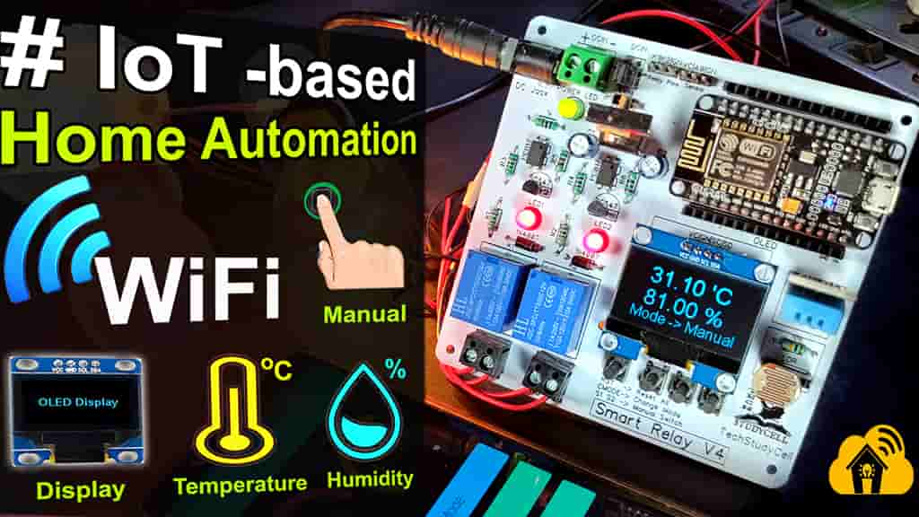
- Manual Mode
- Control relays from the Blynk app and push buttons manually.
- Auto Mode
- Control relays with the DHT11 sensor and LDR automatically.
Table of Contents
Circuit of this Blynk NodeMCU IoT projects

The circuit for this NodeMCU Blynk IoT-based home automation project is very simple.
I have used D5 & D6 GPIO to control the 2 relays. And the GPIO D0, D7 & D8 connected with pushbuttons to control the relay module and to change the mode manually.
The SD3 connected with DHT11 temperature sensor and A0 connected with LDR.
The OLED connected with D1 & D2. Here OLED is optional.
Then input voltage in 12V DC. And I have used 7805 regulator to fed 5V supply to NodeMCU and sensors.
Required Components for this NodeMCU Project:

- NodeMCU
- DH11 Sensor
- LDR
- 10k Resistors (5-no)
- 1k Resistors (5-no) (R1 to R4)
- 220-ohm Resistors 2 no (R5 & R6)
- Optocoupler PC817 2 no
- BC547 NPN Transistors (2-no)
- Diode 1N4007 (2-no)
- Diode 1N4001 (1-no)
- LED (1.5v) (3-no)
- Capacitors 100uF (2-no)
- SPDT 12V Relays (2-no)
- 7805 voltage regulator (1-no)
- Push Switch/ button (4-no)
- Connectors & jumpers
- OLED I2C Display (0.96″ or 1.3″)
Tutorial video on Blynk NodeMCU Home Automation
In this tutorial video, I have explained how to use NodeMCU to make the IoT project. How to configure the Blynk app to control any home appliances through the internet. Also explained how to get sensor data in the Blynk App and program the NodeMCU with Arduino IDE.
PCB for the NodeMCU IoT Projects


Program NodeMCU with Arduino IDE
For this IoT based home automation project, I have used the Arduino IDE to program NodeMCU.
First update the Preferences –> Aditional boards Manager URLs: https://dl.espressif.com/dl/package_esp32_index.json, http://arduino.esp8266.com/stable/package_esp8266com_index.json
Then install the ESP8266 board from the Board manager or Click Here to download ESP8266 Board.
After that install the following libraries.
- Blynk Library: Click Here to download.
- DHT11 Sensor Library: Click Here to download.
- Adafruit_SSD1306 (for 0.96″ OLED display): Click Here to download.
- SH1106Wire Library (for 1.3″ OLED display): Click Here to download.
In the code, you have to enter the AUTH TOKEN & WiFi credentials.
#define AUTH "AUTH TOKEN"                 // You should get Auth Token in the Blynk App.
#define WIFI_SSID "WIFI NAME"             //Enter Wifi Name
#define WIFI_PASS "WIFI PASSWORD"         //Enter wifi Password
And you can modify the predefined temperature and light intensity limit as per your requirement.
//Set values for Auto Control Mode
const float maxTemp = 34.10;
const float minTemp = 33.8;

const int maxLight = 1000;
const int minLight = 200;
After entering this details, upload the code to NodeMCU.
Connect Home Appliances with Relay

Now, connect 2 home appliances with relay module as per the above circuit.
In Auto mode, Relay-1 can be controlled with room temperature, so I have connected a Fan with Relay-1. And Relay-2 can be controlled with LDR (Dark sensor), so I have connected a lamp with Relay-2.
Please take proper safety precaution while working with high voltage.
Control Relays with Blynk App and Pushbuttons

In manual mode, you can easily control the home appliances from the smartphone using Blynk App. And you can also monitor the real time status of switches in the Blynk app when you control the relays manually from push buttons.
Control Relays with LDR and DHT11 temperature sensor

In Auto Mode, the NodeMCU compares the predefined maximum and minimum temperature values with the temperature sensed by the DHT11 sensor. And accordingly, control the Relay-1.
And the Relay-2 controlled by the LDR as per the predefined value mentioned in the code.
I hope you like this Smart house IoT projects idea with the ESP8266 and Blynk app.
Click Here for more such ESP8266 projects.
Please do share your feedback on this IoT project. Thank you for your time.


