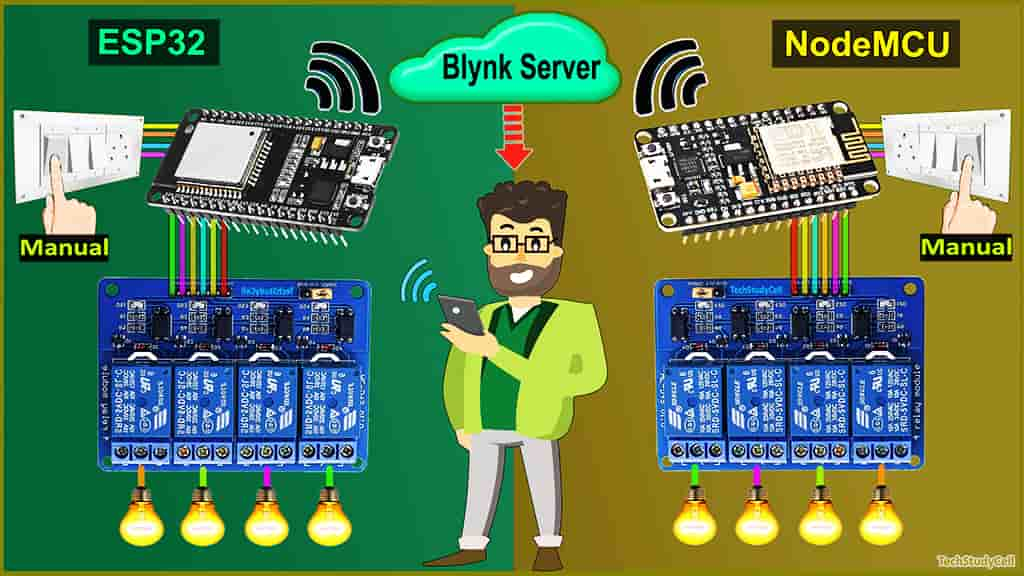
In this internet of things project, I have shown how to make home automation using IoT with ESP32 NodeMCU and Blynk app. With this IoT project, you can control all the home appliances from different rooms with the same Blynk account and manual switches. If there is no WiFi available then you can control the relay module manually with switches.

So you can connect any number of NodeMCU or ESP32 with the same Blynk account to control all the appliances of your home and office.
With this smart home project, you can also monitor the real-time status of each switch in the Blynk app. If WiFi is available the ESP32 or NodeMCU will automatically connect with the WiFi.
Table of Contents
Circuit of the NodeMCU Home Automation using IoT

The circuit is very simple, I have used D1, D2, D5 & D6 GPIO to control the 4-channel relay module.
And the GPIO SD3, D3, D7 & RX are connected with switches to control the relay module manually.
I have used the INPUT_PULLUP function in Arduino IDE instead of using the pull-up resistors with each switch.
As per the source code, when the control pins of the relay module receive the LOW signal the respective relay will turn on and the relay will turn off for the HIGH signal in the control pin.
I have used a 5V 5Amp mobile charger to supply the circuit.
Circuit of the ESP32 Home Automation using IoT

The circuit is very simple, I have used D23, D22, D21 & D19 GPIO to control the 4-channel relay module.
And the GPIO D13, D12, D14 & D27 are connected with switches to control the relay module manually.
I have used the INPUT_PULLUP function in Arduino IDE instead of using the pull-up resistors with each push button.
As per the source code, when the control pins of the relay module receive a LOW signal the relay will turn on and the relay will turn off for the HIGH signal in the control pin.
I have used a 5V 5Amp mobile charger to supply the circuit.

As you see, the connection is very simple. And you can use the existing switchboard to control the relays manually.

For each room you need the following components:
- NodeMCU or ESP32
- 4-channel Relay Module (5V)
- Switches
If you use ESP32 then you can use either 4-channel or 8-channel relay module.
Affiliate Purchase Links:
Tutorial video on ESP32 NodeMCU Blynk Home Automation
In this tutorial video, I have explained how to connect multiple ESP32, NodeMCU ESP8266 IoT networks with the same Blynk account to make this smart home automation system. How to configure the Blynk app to control any home appliances with WiFi. Also explained the code and how to program ESP32 and NodeMCU with Arduino IDE.
Configure the Blynk App:

1. Download the Blynk App from the Google play store or App store.
2. Then Sign Up with your Email Id and tap on “New Project“.
3. Enter the project name and choose the device. In this IoT project, I have selected the device as NodeMCU **. The connection type should be “Wi-Fi“. Then Tap on “Create“.
(**As we will use only virtual pins so we can control both ESP32 and NodeMCU from this Blynk project)
4. After that Blynk will send an Auth Token to the registered email id. The Auth Token will be required while programming the ESP8266.
Adding widgets in Blynk App

Now to control the relay modules you have to add button widgets in Blynk app
Steps to add the button in Blynk App:
1. Open the project in the Blynk App Click on the “+” icon on the top.
2. Select the Button.
3. Tap on that button and select the output pin –> V1 & Mode –> Switch
**Here I have used an active low Relay module, so to turn ON the relay we have to send “0” and “1” to turn OFF the relay.
4. In a similar way create buttons with V2, V3, V4, V5, V6, V7, V8 pins to control the relays.
Here, I have used V1, V2, V3, V4 to control the first relay module. And V5, V6, V7, V8 to control the second relay module.
Now if want to control more relay modules, then you have to add more button widgets as per the number of the relays.

Please refer to the tutorial video for configuring the Blynk App.
Program NodeMCU & ESP32 with Arduino IDE
For this IoT based home automation project, I have used the Arduino IDE to program NodeMCU.
First update the Preferences –> Aditional boards Manager URLs: https://dl.espressif.com/dl/package_esp32_index.json, http://arduino.esp8266.com/stable/package_esp8266com_index.json
- Then install the ESP8266 board from the Board manager or Click Here to download the ESP8266 boards.
- Then install the ESP32 board from the Board manager or Click Here to download the ESP32 board.
- After that install the Blynk library. Click Here to download the Blynk library.
- Then install the AceButton library. Click Here to download the AceButton library.
Codes for Blynk Home Automation Project
Enter the following WiFi credential and Authentication token in the code:
- WiFi Name at “WIFI Name”
- WiFi Password at “WIFI Password”
- Auth Token sent by Blynk at “AUTH TOKEN“
Then go to Tools and for NodeMCU select the board as “NodeMCU 1.0 ESP-12E” and for ESP32 select board as “DOIT ESP32 DEVKIT V1“. Then select the proper PORT in Arduino IDE.
Then click on the upload button to program the NodeMCU or ESP32 board.
Important points to remember
- In code, you have to change only the virtual pins according to the NodeMCU or ESP32 numbers.
- You can use different WiFi networks for each microcontroller, but the Authentication Token must be the same for all the NodeMCUs and ESP32.
- Don’t connect both microcontrollers with the laptop at the same time.
- If ESP32 keeps rebooting after code uploaded then use another power supply.
- To control the appliances from different mobiles, you have to log in to the same Blynk account from all the smartphones.
Control Relays with Blynk App

Now, if the ESP32 or NodeMCU connected with the WiFi, then you can control all appliances from anywhere in the world, and also monitor the relay-time feedback of each relay in the Blynk App.
Here, I have connected one NodeMCU and one ESP32 with the Blynk server. But as I mentioned, you can connect multiple NodeMCU and ESP32 as per your requirements.
Control Relays Manually from Switches

Controlling Relays Manually from Switches 
Controlling Relays without WiFi
With this home automation system, you can always control the appliances manually with Switches.
And if the NodeMCU and ESP32 are connected with WiFi, it will send real-time feedback to the Blynk server.
I hope you like this Smart house IoT projects idea with multiple NodeMCU ESP8266 and Blynk app.
Click Here for more such ESP32 projects.
Please do share your feedback on this IoT project. Thank you for your time.


