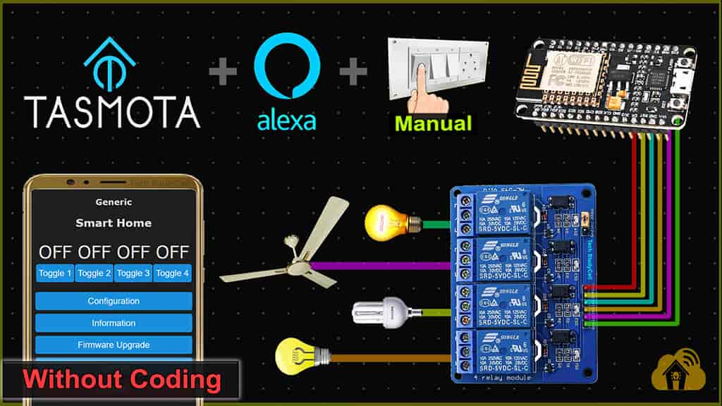
In this IoT project, I have explained how to make the Tasmota NodeMCU ESP8266 Home Automation project to control 4 relays with Amazon Alexa and manual switches without writing a single line code.

This Tasmota ESP8266 home automation system has the following features:
- Control 4 appliances with Amazon Alexa.
- Control 4 appliances manually with switches or pushbuttons.
- Control the ESP8266 without internet.
- Get real-time feedback in the Alexa app.
- ESP8266 remembers the last state after the power cut.
- All the tools used are FREE & open source.
Table of Contents
Required Components for ESP8266 Home Automation

- NodeMCU ESP8266 Amazon
- 4-channel 5V SPDT Relay Module Amazon
- Switches or Pushbuttons Amazon
- Amazon Echo Dot Amazon
Circuit of the ESP8266 Home Automation

The circuit is very simple, I have used D1, D2, D5 & D6 GPIO pins to control the 4-channel relay module.
And the GPIO SD3, D3, D7 & RX are connected with the pushbuttons to control the relay module manually.
I have used the INPUT_PULLUP function in Arduino IDE instead of using the pull-up resistors with each switch.
As per the source code, when the control pins of the relay module receive the LOW signal the respective relay will turn on and the relay will turn off for the HIGH signal in the control pin.
**If you use switch (latched), the Boot will fail if SD3 and D3 are grounded during the Boot process. So manual switch-S1 and switch-S2 must be OFF during NodeMCU Boot.
Now, if you want to use pushbuttons then just connect the pushbuttons across the GPIO pins and GND pin instead of switches.
I have used a 5V 5Amp mobile charger to supply the circuit.
Tutorial video on Tasmota ESP8266 Project
In the Tasmota ESP8266 tutorial video, I have covered the following topics.
- Download the Tasmotizer from Github.
- Flash ESP8266 with Tasmota firmware.
- Configure Tasmota for ESP8266 NodeMCU.
- Connect Tasmota devices with Amazon Alexa.
Download the required files to flash ESP8266
You need the following files to flash the tasmota firmware to ESP8266 NodeMCU.
Here, I have used the tasmota.bin firmware for this project.
If you have a 32-bit system then download the tasmotizer_x86-1.2.exe instead of tasmotizer-1.2.exe from Github.
Flash the ESP8266 NodeMCU with Tasmota firmware
Follow these steps to flash the ESP8266 with Tasmota firmware and update the WiFi credentials to get the IP for Tasmota Dashboard.
-
Flash ESP8266 with Tasmota firmware

Connect the NodeMCU ESP8266 with the laptop. Open the Tasmotizer.exe.
Then select the port from the drop-down list.
Select the BIN file. Click on “Open” and browse the tasmota.bin which you have downloaded.
Check the “Self-resetting device” and “Erase before flashing“.
Click on “Tasmotize“. -
Configure Wi-Fi

After that click on the “Send config” button. Then check the WiFi box and enter the WiFi credentials.
Click on Save and wait for 5 seconds. -
Get the IP to access Tasmota Dashboard

To get the IP click on the “Get IP” button.
Copy the IP address then paste it into the browser to open the Tasmota Dashboard.
Configure the ESP8266 GPIO pins in Tasmota dashboard
Follow these steps to configure the GPIO pins of ESP8266 NodeMCU in the Tasmota Dashboard.
Select the Module Type:

First, click on the “Configuration” button.

Then click on “Configure Module“.

Select the module type as Generic (0).
Then click in Save and go to Main Menu.
Now again, you have to click on “Configuration“, then click on “Configure Module“.
Configure the GPIO pins in Tasmota Dashboard

Now you have to configure the GPIO pins connected with the relays and switches.
In this project, I have used an active low (Relay will turn on for LOW signal at control pin) relay module. So I have selected “Relay_i” for the GPIO pins connected with Relay.
If you use the active HIGH relay module, then select “Relay“.
If you use push buttons (momentary switch), then select “Button” for all the GPIO connected with push buttons. But if you use switch (latched), then select “Switch“.
You also have to select the number to map each switch with the respective relay.
Here the GPIO-5 (D1) connected with Relay-1 and the GPIO-10 (SD3) connected with switch-1, so for these two GPIO pins, I have selected the number as “1“.
Thus, you have to map all the GPIO pins as per the circuit.
Then Click on “Save” and go to “Main Menu“.

Now you will find 4 buttons added in the Tasmota dashboard.
To control the relays, just click on these buttons. You can also monitor the real-time feedback when you control the relays with push buttons.
Tasmota Alexa Integration for ESP8266
You can interact with Tasmota devices using Amazon Alexa through its Echo devices to control with voice commands.
Please refer to the following article for the step-by-step guide.
Control the appliances with Alexa

After adding all the Tasmota devices to Amazon Alexa App, you can ask Alexa to turn on/off the light.
You can also monitor the real-time feedback in the Amazon Alexa app.
The Echo Dot and the ESP8266 must be connected with the same Wi-Fi network.
Control the ESP8266 without internet
You can also control the relay with switches or push buttons if there is no internet.
The ESP8266 can remember the last state so after the power cut the appliances will turn on as per the previous state.
PCB for the Tasmota NodeMCU Smart Home Project

If you want, you can also use this PCB to make the circuit compact and give the project a professional look.
Click Here for more such ESP8266 projects.
Please do share your feedback on this IoT project. Thank you for your time.


