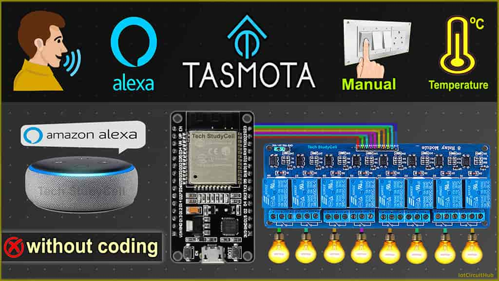
In this ESP32 project, I have explained how to make the Tasmota ESP32 Alexa voice control home automation system to control 8 relays from the Amazon Alexa app and manual switches. You can also connect the DHT11 sensor with Tasmota and monitor the room temperature.

This Tasmota ESP32 home automation system has the following features:
- Control 8 appliances with Amazon Alexa voice control.
- Control 8 appliances manually with switches or pushbuttons.
- Control the ESP32 without internet.
- Get real-time feedback in the Amazon Alexa app.
- Monitor room temperature with DHT11 sensor
- All the tools used are FREE & open source.
Table of Contents
Required Components for Tasmota ESP32 project

- ESP32 DEVKIT VT Amazon
- 8-channel 5V SPDT Relay Module Amazon
- DHT11 Sensor Amazon
- Switches or Pushbuttons Amazon
- Amazon Echo Dot Amazon
Circuit of the Tasmota ESP32 Home Automation

The circuit is very simple, I have used D23, D22, D21, D19, D18, D5, D25 & D26 GPIO pins to control the 8-channel relay module.
And the GPIO D13, D12, D14, D27, D33, D32, D15 & D4 are connected with switches to control the relay module manually.
The output pin of the DHT11 sensor is connected with the RX2 (GPIO16) pin of the ESP32.
I have used the INPUT_PULLUP function in Arduino IDE instead of using the pull-up resistors with each switch.
As per the source code, when the control pins of the relay module receive a LOW signal the relay will turn on and the relay will turn off for the HIGH signal in the control pin.
I have used a 5V 5Amp mobile charger to supply the circuit.
If you want to use the push buttons (momentary switch) then refer to the following circuit

You can also connect a 4-channel relay module with ESP32 to control 4 appliances. Please refer to the following circuit for that.

Tutorial video on Tasmota ESP8266 Project
In the Tasmota ESP8266 tutorial video, I have covered the following topics.
- Download the Tasmota firmware and ESP Flasher tool from Github.
- Flash ESP32 with Tasmota firmware.
- Configure Tasmota for ESP32 control relays and sensor.
- Connect Tasmota devices with Amazon Alexa.
Download the required files to flash ESP32
You need the following files to flash the tasmota firmware to ESP32.
Here, I have used the tasmota32.bin firmware for this project.
And download the ESP Flasher tools as per the system (32-bit/64-bit, Windows/MAC) you are using.
Flash the ESP32 with Tasmota firmware
Follow these steps to flash the ESP32 with Tasmota firmware and update the WiFi credentials to get the IP to access the Tasmota Dashboard.
-
Flash ESP32 with Tasmota firmware

Connect the ESP32 with the laptop. Open the ESP-Flasher.exe.
Then select the Serial port from the drop-down list.
Select the BIN file. Click on “Browse” and open the tasmota32.bin which you have downloaded.
Click on “Flash ESP“. -
Press the BOOT button of ESP32

After click on the Flash ESP button, you have to press and hold the BOOT button of ESP32 until the Flasing starts.
-
Get the IP to Update Wi-Fi details to ESP32

Once the flashing is complete, you will get the hotspot name and IP.
Connect with the hotspot, then enter the IP in the browser. -
Update Wi-Fi details to ESP32

Now, enter the Wi-Fi name and password. Then click on “Save”.
Wait for 5-10 seconds. -
Copy the IP to access the Tasmota Dashboard

After saving the WiFi details, you will get the IP to access the Tasmota Dashboard.
Copy the IP, then connect with the Wi-Fi.
Now open a browser and paste the IP to open the Tasmota Dashboard.
Configure the ESP32 GPIO pins in Tasmota dashboard
Follow these steps to configure GPIO pins of ESP32 in the Tasmota Dashboard.

In the Tasmota Dashboard, click on the “Configuration” button.

Then click on “Configure Module“.

Now you have to configure all the GPIO pins connected with the relays and switches.
Here, I have used an active-LOW (Relay will turn on for LOW signal at control pin) relay module. So I have selected “Relay_i” for the GPIO pins, connected with relays.
If you use the active-HIGH relay module, then select “Relay“.
If you use push buttons (momentary switch), then select “Button” for all the GPIO connected with push buttons. But if you use switch (latched), then select “Switch“.
You also have to select the number to map each switch with the respective relay.
Here the GPIO23 connected with Relay-1 and the GPIO13 connected with switch-1, so for these two GPIO pins, I have selected the number as “1“.
In the circuit, the DHT11 sensor is connected with GPIO16, so I have selected “DHT11” for GPIO16. If you use any other sensor, then accordingly select the sensor type from the dropdown.
Thus, you have to map all the GPIO pins as per the circuit.
After that, click on “Save” and go to “Main Menu“.

Now you will find 8 buttons added in the Tasmota dashboard.
To control the relays, just click on these buttons. You can also monitor the real-time feedback when you control the relays with push buttons or switches.
Tasmota Alexa Integration for ESP32
You can also interact with Tasmota devices using Amazon Alexa through its Echo devices to control with voice commands.
Please refer to the following article for the step-by-step guide.
PCB for the Tasmota ESP32 Smart Home Project
To make the circuit compact, I have designed a PCB for this ESP32 project.
If you want, you can also use this PCB to make the circuit compact and give the project a professional look.

About PCBWay and their services
You can order any custom design PCB from PCBWay at a very reasonable price.
PCBWay not only produces FR-4 and Aluminum boards but also advanced PCBs like Rogers, HDI, Flexible and Rigid-Flex boards, at very affordable prices.
For the online instant quote page please visit – pcbway.com/orderonline
PCBWay also offers an Assembly service. The online pricing software can instantly quote for your PCB Assembly service through a rough calculation. Their PCBA prices are very reasonable.
Rough quote online – pcbway.com/pcb-assembly
You can also explore different PCB projects from their Open-source community pcbway.com/project/.
For more details please visit the following articles.
Why PCBway
PCB Capabilities
High-Quality PCB
Steps to order PCB from PCBWay
To order the PCB first visit PCBWay.com.

Then enter the following details:
- PCB Size (Length & Width) in mm & PCB quantity
- Select masking color for the PCB
- Select country and shipping method
- Click on the “Save to Cart” button

Now click on the “Add Gerber Files” to upload the PCB Gerber file.
Then click on the “Submit Order Now” to place the order.
After that, they will review the Gerber file and accordingly confirm the order.
I have used their services for my different home automation projects, I always received the PCB on time and the quality is very good in this price range.
Connect Home Appliances with Relay Module

Connect the home appliances with the relay module as per the circuit diagram.
The external switches are optional, you can use only push buttons.
Now, turn on the 5V DC supply and 110V/220V AC supply.
Control the appliances with Tasmota Alexa

After adding all the Tasmota devices to Amazon Alexa App, you can ask Alexa to turn on/off the light.
You can also monitor the real-time feedback in the Amazon Alexa app.
The Echo Dot and the ESP32 must be connected with the same Wi-Fi network.
Control the ESP32 without internet
You can also control the relay with switches or push buttons if there is no internet.
When the internet comes back, the ESP32 will automatically connect with the Wi-Fi.
Click Here for more such ESP32 projects.
Please do share your feedback on this IoT project. Thank you for your time.


