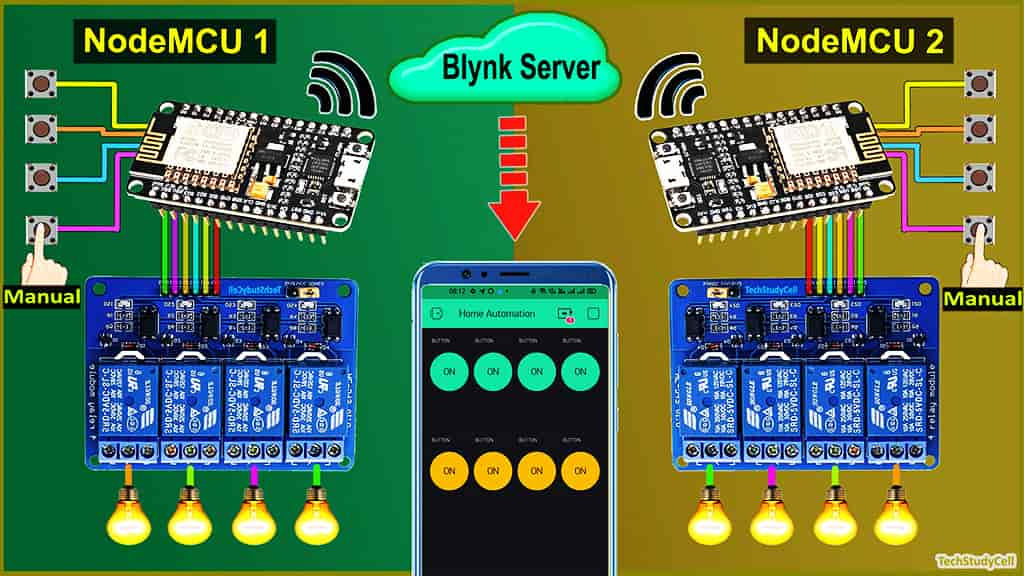
In this ESP8266 Blynk project, I have shown how to make a home automation system using multiple NodeMCU ESP8266 networks with Blynk. With this IoT project, you can control all the home appliances from different rooms with the same Blynk account and manual switches. If there is no WiFi available then you can control the relay module from the pushbuttons.

So you can connect any number of NodeMCUs or ESP8266 with the same Blynk account to control all the appliances of your home and office.
With this smart home project, you can also monitor the real-time status of each switch in the Blynk app. If WiFi is available the NodeMCU will automatically connect with the WiFi.
Table of Contents
Circuit of the NodeMCU Home Automation

The circuit is very simple, I have used D1, D2, D5 & D6 GPIO to control the 4-channel relay module.
And the GPIO SD3, D3, D7 & RX connected with pushbuttons to control the relay module manually.
I have used the INPUT_PULLUP function in Arduino IDE instead of using the pull-up resistors with each switch.
As per the source code, when the control pins of the relay module receive the LOW signal the respective relay will turn on and the relay will turn off for the HIGH signal in the control pin.
I have used a 5V 2Amp mobile charger to supply the circuit.

Now if you have two rooms, then you can use 2 NodeMCUs and 2 Relay Modules as following:

In similar way you have to add NodeMCU to the network as per the room number. There is no limitation with the number of NodeMCU or ESP8266 that you can connect with this networks.
Required Components for Blynk ESP8266 Project:

For each room you need following components:
- NodeMCU
- 4-channel Relay Module (5V)
- Push Buttons 4nos
Tutorial video on ESP8266 Blynk Home Automation
In this tutorial video, I have explained how to connect multiple NodeMCU ESP8266 networks with the same Blynk account to make this home automation system. how to configure the Blynk app to control any home appliances through the internet. Also explained the code and how to program ESP8266 with Arduino IDE.
Configure the Blynk App:

1. Download the Blynk App from Google play store or App store.
2. Then Sign Up with Email Id and tap on “New Project“.
3. Enter the project name and choose the device. In this IoT project, I have used NodeMCU, so I have selected NodeMCU. The connection type should be “Wi-Fi“. Then Tap on “Create“.
4. After that Blynk will send an Auth Token to the registered email id. The Auth Token will be required while programming the ESP8266.
Adding widgets in Blynk App

Now to control the relay modules you have to add button widgets in Blynk app
Steps to add the button in Blynk App:
1. Open the project in the Blynk App Click on the “+” icon on the top.
2. Select the Button.
3. Tap on that button and select the output pin –> V1 & Mode –> Switch
**Here I have used an active low Relay module, so to turn ON the relay we have to send “0” and “1” to turn OFF the relay.
4. In a similar way create buttons with V2, V3, V4, V5, V6, V7, V8 pins to control the relays.
Here, I have used V1, V2, V3, V4 to control the first relay module. And V5, V6, V7, V8 to control the second relay module.
Now if want to control more relay modules, then you have to add more button widgets as per the relays number.
Please refer the tutorial video for configuring the Blynk App.

Program NodeMCU with Arduino IDE
For this IoT based home automation project, I have used the Arduino IDE to program NodeMCU.
First update the Preferences –> Aditional boards Manager URLs: https://dl.espressif.com/dl/package_esp32_index.json, http://arduino.esp8266.com/stable/package_esp8266com_index.json
Then install the ESP8266 board from the Board manager or Click Here to download ESP8266 Board.
After that install the Blynk library. Click Here to download the Blynk library.
Code for Blynk Home Automation Project
#include <BlynkSimpleEsp8266.h>

// define the GPIO connected with Relays and switches
#define RelayPin1 5  //D1
#define RelayPin2 4  //D2
#define RelayPin3 14 //D5
#define RelayPin4 12 //D6

#define SwitchPin1 10  //SD3
#define SwitchPin2 0   //D3
#define SwitchPin3 13  //D7
#define SwitchPin4 3   //RX

#define wifiLed   16   //D0

//Change the virtual pins according the rooms
#define VPIN_BUTTON_1    V1
#define VPIN_BUTTON_2    V2
#define VPIN_BUTTON_3    V3
#define VPIN_BUTTON_4    V4

int toggleState_1 = 1; //Define integer to remember the toggle state for relay 1
int toggleState_2 = 1; //Define integer to remember the toggle state for relay 2
int toggleState_3 = 1; //Define integer to remember the toggle state for relay 3
int toggleState_4 = 1; //Define integer to remember the toggle state for relay 4

int wifiFlag = 0;

#define AUTH "AUTH TOKEN"                 // You should get Auth Token in the Blynk App.
#define WIFI_SSID "Wifi Name"             //Enter Wifi Name
#define WIFI_PASS "Wifi Password"         //Enter wifi Password

BlynkTimer timer;

void relayOnOff(int relay){
    switch(relay){
      case 1:
             if(toggleState_1 == 1){
              digitalWrite(RelayPin1, LOW); // turn on relay 1
              toggleState_1 = 0;
              Serial.println("Device1 ON");
              }
             else{
              digitalWrite(RelayPin1, HIGH); // turn off relay 1
              toggleState_1 = 1;
              Serial.println("Device1 OFF");
              }
             delay(100);
      break;
      case 2:
             if(toggleState_2 == 1){
              digitalWrite(RelayPin2, LOW); // turn on relay 2
              toggleState_2 = 0;
              Serial.println("Device2 ON");
              }
             else{
              digitalWrite(RelayPin2, HIGH); // turn off relay 2
              toggleState_2 = 1;
              Serial.println("Device2 OFF");
              }
             delay(100);
      break;
      case 3:
             if(toggleState_3 == 1){
              digitalWrite(RelayPin3, LOW); // turn on relay 3
              toggleState_3 = 0;
              Serial.println("Device3 ON");
              }
             else{
              digitalWrite(RelayPin3, HIGH); // turn off relay 3
              toggleState_3 = 1;
              Serial.println("Device3 OFF");
              }
             delay(100);
      break;
      case 4:
             if(toggleState_4 == 1){
              digitalWrite(RelayPin4, LOW); // turn on relay 4
              toggleState_4 = 0;
              Serial.println("Device4 ON");
              }
             else{
              digitalWrite(RelayPin4, HIGH); // turn off relay 4
              toggleState_4 = 1;
              Serial.println("Device4 OFF");
              }
             delay(100);
      break;
      default : break;
      }
}

void with_internet(){
    //Manual Switch Control
    if (digitalRead(SwitchPin1) == LOW){
      delay(200);
      relayOnOff(1);
      Blynk.virtualWrite(VPIN_BUTTON_1, toggleState_1);   // Update Button Widget
    }
    else if (digitalRead(SwitchPin2) == LOW){
      delay(200);
      relayOnOff(2);
      Blynk.virtualWrite(VPIN_BUTTON_2, toggleState_2);   // Update Button Widget
    }
    else if (digitalRead(SwitchPin3) == LOW){
      delay(200);
      relayOnOff(3);
      Blynk.virtualWrite(VPIN_BUTTON_3, toggleState_3);   // Update Button Widget
    }
    else if (digitalRead(SwitchPin4) == LOW){
      delay(200);
      relayOnOff(4);
      Blynk.virtualWrite(VPIN_BUTTON_4, toggleState_4);   // Update Button Widget
    }
}
void without_internet(){
    //Manual Switch Control
    if (digitalRead(SwitchPin1) == LOW){
      delay(200);
      relayOnOff(1);
    }
    else if (digitalRead(SwitchPin2) == LOW){
      delay(200);
      relayOnOff(2);
    }
    else if (digitalRead(SwitchPin3) == LOW){
      delay(200);
      relayOnOff(3);
    }
    else if (digitalRead(SwitchPin4) == LOW){
      delay(200);
      relayOnOff(4);
    }
}

// When App button is pushed - switch the state
BLYNK_WRITE(VPIN_BUTTON_1) {
  toggleState_1 = param.asInt();
  digitalWrite(RelayPin1, toggleState_1);
}

BLYNK_WRITE(VPIN_BUTTON_2) {
  toggleState_2 = param.asInt();
  digitalWrite(RelayPin2, toggleState_2);
}

BLYNK_WRITE(VPIN_BUTTON_3) {
  toggleState_3 = param.asInt();
  digitalWrite(RelayPin3, toggleState_3);
}

BLYNK_WRITE(VPIN_BUTTON_4) {
  toggleState_4 = param.asInt();
  digitalWrite(RelayPin4, toggleState_4);
}

void checkBlynkStatus() { // called every 3 seconds by SimpleTimer

  bool isconnected = Blynk.connected();
  if (isconnected == false) {
    wifiFlag = 1;
  }
  if (isconnected == true) {
    wifiFlag = 0;
    Blynk.virtualWrite(VPIN_BUTTON_1, toggleState_1);
    Blynk.virtualWrite(VPIN_BUTTON_2, toggleState_2);
    Blynk.virtualWrite(VPIN_BUTTON_3, toggleState_3);
    Blynk.virtualWrite(VPIN_BUTTON_4, toggleState_4);
  }
}
void setup()
{
  Serial.begin(9600);

  pinMode(RelayPin1, OUTPUT);
  pinMode(RelayPin2, OUTPUT);
  pinMode(RelayPin3, OUTPUT);
  pinMode(RelayPin4, OUTPUT);

  pinMode(wifiLed, OUTPUT);

  pinMode(SwitchPin1, INPUT_PULLUP);
  pinMode(SwitchPin2, INPUT_PULLUP);
  pinMode(SwitchPin3, INPUT_PULLUP);
  pinMode(SwitchPin4, INPUT_PULLUP);

  //During Starting all Relays should TURN OFF
  digitalWrite(RelayPin1, toggleState_1);
  digitalWrite(RelayPin2, toggleState_2);
  digitalWrite(RelayPin3, toggleState_3);
  digitalWrite(RelayPin4, toggleState_4);

  digitalWrite(wifiLed, HIGH);

  WiFi.begin(WIFI_SSID, WIFI_PASS);
  timer.setInterval(3000L, checkBlynkStatus); // check if Blynk server is connected every 3 seconds
  Blynk.config(AUTH);
  delay(1000);

  Blynk.virtualWrite(VPIN_BUTTON_1, toggleState_1);
  Blynk.virtualWrite(VPIN_BUTTON_2, toggleState_2);
  Blynk.virtualWrite(VPIN_BUTTON_3, toggleState_3);
  Blynk.virtualWrite(VPIN_BUTTON_4, toggleState_4);
}

void loop()
{
  if (WiFi.status() != WL_CONNECTED)
  {
    //Serial.println("WiFi Not Connected");
    digitalWrite(wifiLed, HIGH);
  }
  else
  {
    //+Serial.println("WiFi Connected");
    digitalWrite(wifiLed, LOW); //Turn on WiFi LED
    Blynk.run();
  }

  timer.run(); // Initiates SimpleTimer
  if (wifiFlag == 0)
    with_internet();
  else
    without_internet();
}
Enter the following WiFi credential and Authentication token in the code:
- WiFi Name at “WiFi Name”
- WiFi Password at “WiFi Password”
- Auth Token sent by Blynk at “AUTH TOKEN“
Then Goto Tools and select the board as “NodeMCU 1.0 ESP-12E” and the proper PORT in Arduino IDE.
Then click on the upload button to program the NodeMCU board.

After uploading the code, if Wi-Fi is available, the blue LED connected with pin D0 should turn on as shown in the picture.
If the Wi-Fi is not available, the blue LED will turn off. Then you can control the relay module with push buttons.
If the internet comes back the NodeMCU will automatically connect with the WiFi and the blue LED will turn on.
Connect Home Appliances with Relay

Now, connect the home appliances with relay module as per the above circuit. For each room you can connect 4 appliances.
Please take proper safety precaution while working with high voltage.
Control Relays with Blynk App

Now, if the NodeMCU ESP8266 connected with the WiFi, then you can control all appliances from anywhere in the world, and also monitor the relay-time feedback of each relay in the Blynk App.
Here, I have connected two NodeMCUs with the Blynk server. But as I mentioned, you can connect multiple NodeMCU as per your requirements.
Control Relays Manually from Push-Buttons

With this home automation system, you can always control the appliances manually with pushbuttons.
And if the NodeMCU is connected with WiFi, it will send the real-time feedback to the Blynk server.
I hope you like this Smart house IoT projects idea with multiple NodeMCU ESP8266 and Blynk app.
Click Here for more such ESP8266 projects.
Please do share your feedback on this IoT project. Thank you for your time.


