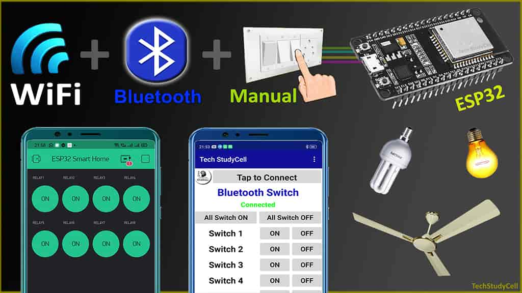
In this internet of things project, I have explained how to make the ESP32 WiFi Bluetooth smart home system with manual switches and the Blynk app to control an 8-channel relay module.

If the WiFi is available then you can control the home appliances with the Blynk app. If there is no internet, still you can control the relays from the smartphone using Bluetooth. You can also turn ON and turn OFF the home appliances from switches or push buttons.
In this article, I have explained all the steps to make this smart home system using ESP32 and relay module.
Table of Contents
Circuit of the ESP32 Smart Home System

**If you are using push-buttons instead of switches then please refer to the following circuit

I have used D23, D22, D21, D19, D18, D5, D25 & D26 GPIO to control the 8 relays.
And the GPIO D13, D12, D14, D27, D33, D32, D15 & D4 connected with manual switches to control the relay module manually.
You can also connect push buttons across the GPIOs and GND pin instead of switches.
I have used the INPUT_PULLUP function in Arduino IDE instead of using the pull-up resistors with each switch.
As per the source code, when the control pins of the relay module receive the LOW signal the respective relay will turn on and the relay will turn off for the HIGH signal in the control pin.
I have used a 5V 2Amp mobile charger to supply the circuit.
Required Components for the ESP32 projects

- ESP32 DEV KIT V1
- 8-channel 5V SPDT Relay Module
- Manual Switches or Push Buttons
Tutorial video on ESP32 WiFi Bluetooth project
In the tutorial video, I have explained all the steps on how to make this smart home system with ESP32 WiFi and Bluetooth. Please watch the complete video for a better understanding.
Configure the Blynk App for ESP32

1. Download & install the Blynk App from Google play store or App store. Then sign up.
2. Create a new project in the Blynk app. Enter the project name and choose the device as ESP32 Dev Board. Then tap on Create.
3. After that Blynk will send an Auth Token to the registered email id. The Auth Token will be required while programming the ESP32.
Adding Button widgets in Blynk App

Now to control the 8-channel relay module you have to add 8 button widgets in the Blynk app
Steps to add buttons in the Blynk App:
- Open the project in the Blynk App Click on the “+” icon on the top. select the Button.
- Tap on that button and select the output pin –> V1 & Mode –> Switch. You can also give any name to that button. Here, I have used an active low Relay module, so to turn ON the relay we have to send “0” and “1” to turn OFF the relay.
- In a similar way create buttons with V2, V3, V4, V5, V6, V7, V8 pins to control the second, third, fourth, fifth, sixth, seventh & eighth relays.
Please refer the tutorial video for configuring the Blynk App.
Bluetooth App for ESP32 project
To control the ESP32 with Bluetooth, I have designed a Bluetooth App in MIT App Inventor.
Download the Bluetooth Switch App and install it. I have not submitted the App to Google Play Store. So you may get an alert while installing the App.
I have already published an article on ESP32 Bluetooth control Relay. Please visit the article for more details.
Program ESP32 with Arduino IDE
In the Tutorial video, I have explained all the steps to program the ESP32 DEV KIT V1 using Arduino IDE.
- Update the Preferences –> Aditional boards Manager URLs: https://dl.espressif.com/dl/package_esp32_index.json, http://arduino.esp8266.com/stable/package_esp8266com_index.json
- Then install the ESP32 board from the Board manager or Click Here to download the ESP32 board.
- Download the required libraries from the following links:
- BluetoothSerial Library: Click Here
- AceButton Library: Click Here
- Blynk Library: Click Here
**For this project, you have to install the old version of the ESP32 board (1.0.3 version). Otherwise, you may get the following error.
ERROR: Sketch uses 1333170 bytes (101%) of program storage space.
**Please download the latest version of the libraries from the given links. Then install the libraries at Arduino IDE – Sketch – Include Library – Add Zip Library.
Code for ESP32 WiFi & Bluetooth controlled Relays
#include <BlynkSimpleEsp32.h>
#include "BluetoothSerial.h"
#include <AceButton.h>
using namespace ace_button;


#if !defined(CONFIG_BT_ENABLED) || !defined(CONFIG_BLUEDROID_ENABLED)
#error Bluetooth is not enabled! Please run
`make menuconfig` to and enable it
#endif

BluetoothSerial SerialBT;

BlynkTimer timer;

// define the GPIO connected with Relays and switches
#define RelayPin1 23  //D23
#define RelayPin2 22  //D22
#define RelayPin3 21  //D21
#define RelayPin4 19  //D19
#define RelayPin5 18  //D18
#define RelayPin6 5   //D5
#define RelayPin7 25  //D25
#define RelayPin8 26  //D26

#define SwitchPin1 13  //D13
#define SwitchPin2 12  //D12
#define SwitchPin3 14  //D14
#define SwitchPin4 27  //D27
#define SwitchPin5 33  //D33
#define SwitchPin6 32  //D32
#define SwitchPin7 15  //D15
#define SwitchPin8 4   //D4

#define wifiLed    2   //D2

#define VPIN_BUTTON_1    V1
#define VPIN_BUTTON_2    V2
#define VPIN_BUTTON_3    V3
#define VPIN_BUTTON_4    V4
#define VPIN_BUTTON_5    V5
#define VPIN_BUTTON_6    V6
#define VPIN_BUTTON_7    V7
#define VPIN_BUTTON_8    V8

int toggleState_1 = 1; //Define integer to remember the toggle state for relay 1
int toggleState_2 = 1; //Define integer to remember the toggle state for relay 2
int toggleState_3 = 1; //Define integer to remember the toggle state for relay 3
int toggleState_4 = 1; //Define integer to remember the toggle state for relay 4
int toggleState_5 = 1; //Define integer to remember the toggle state for relay 5
int toggleState_6 = 1; //Define integer to remember the toggle state for relay 6
int toggleState_7 = 1; //Define integer to remember the toggle state for relay 7
int toggleState_8 = 1; //Define integer to remember the toggle state for relay 8

int wifiFlag = 0;
char bt_data; // variable for storing bluetooth data

ButtonConfig config1;
AceButton button1(&config1);
ButtonConfig config2;
AceButton button2(&config2);
ButtonConfig config3;
AceButton button3(&config3);
ButtonConfig config4;
AceButton button4(&config4);
ButtonConfig config5;
AceButton button5(&config5);
ButtonConfig config6;
AceButton button6(&config6);
ButtonConfig config7;
AceButton button7(&config7);
ButtonConfig config8;
AceButton button8(&config8);

void handleEvent1(AceButton*, uint8_t, uint8_t);
void handleEvent2(AceButton*, uint8_t, uint8_t);
void handleEvent3(AceButton*, uint8_t, uint8_t);
void handleEvent4(AceButton*, uint8_t, uint8_t);
void handleEvent5(AceButton*, uint8_t, uint8_t);
void handleEvent6(AceButton*, uint8_t, uint8_t);
void handleEvent7(AceButton*, uint8_t, uint8_t);
void handleEvent8(AceButton*, uint8_t, uint8_t);

#define AUTH "AUTH TOKEN"                 // You should get Auth Token in the Blynk App.
#define WIFI_SSID "WiFi Name"             //Enter Wifi Name
#define WIFI_PASS "WiFi Password"           //Enter wifi Password

// When App button is pushed - switch the state

BLYNK_WRITE(VPIN_BUTTON_1) {
  toggleState_1 = param.asInt();
  digitalWrite(RelayPin1, toggleState_1);
}

BLYNK_WRITE(VPIN_BUTTON_2) {
  toggleState_2 = param.asInt();
  digitalWrite(RelayPin2, toggleState_2);
}

BLYNK_WRITE(VPIN_BUTTON_3) {
  toggleState_3 = param.asInt();
  digitalWrite(RelayPin3, toggleState_3);
}

BLYNK_WRITE(VPIN_BUTTON_4) {
  toggleState_4 = param.asInt();
  digitalWrite(RelayPin4, toggleState_4);
}

BLYNK_WRITE(VPIN_BUTTON_5) {
  toggleState_5 = param.asInt();
  digitalWrite(RelayPin5, toggleState_5);
}

BLYNK_WRITE(VPIN_BUTTON_6) {
  toggleState_6 = param.asInt();
  digitalWrite(RelayPin6, toggleState_6);
}

BLYNK_WRITE(VPIN_BUTTON_7) {
  toggleState_7 = param.asInt();
  digitalWrite(RelayPin7, toggleState_7);
}

BLYNK_WRITE(VPIN_BUTTON_8) {
  toggleState_8 = param.asInt();
  digitalWrite(RelayPin8, toggleState_8);
}

BLYNK_CONNECTED() {
  // Request the latest state from the server
  Blynk.syncVirtual(VPIN_BUTTON_1);
  Blynk.syncVirtual(VPIN_BUTTON_2);
  Blynk.syncVirtual(VPIN_BUTTON_3);
  Blynk.syncVirtual(VPIN_BUTTON_4);
  Blynk.syncVirtual(VPIN_BUTTON_5);
  Blynk.syncVirtual(VPIN_BUTTON_6);
  Blynk.syncVirtual(VPIN_BUTTON_7);
  Blynk.syncVirtual(VPIN_BUTTON_8);
}


void all_Switch_ON(){
  digitalWrite(RelayPin1, LOW); toggleState_1 = 0; delay(100);
  digitalWrite(RelayPin2, LOW); toggleState_2 = 0; delay(100);
  digitalWrite(RelayPin3, LOW); toggleState_3 = 0; delay(100);
  digitalWrite(RelayPin4, LOW); toggleState_4 = 0; delay(100);
  digitalWrite(RelayPin5, LOW); toggleState_5 = 0; delay(100);
  digitalWrite(RelayPin6, LOW); toggleState_6 = 0; delay(100);
  digitalWrite(RelayPin7, LOW); toggleState_7 = 0; delay(100);
  digitalWrite(RelayPin8, LOW); toggleState_8 = 0; delay(100);
}

void all_Switch_OFF(){
  digitalWrite(RelayPin1, HIGH); toggleState_1 = 1; delay(100);
  digitalWrite(RelayPin2, HIGH); toggleState_2 = 1; delay(100);
  digitalWrite(RelayPin3, HIGH); toggleState_3 = 1; delay(100);
  digitalWrite(RelayPin4, HIGH); toggleState_4 = 1; delay(100);
  digitalWrite(RelayPin5, HIGH); toggleState_5 = 1; delay(100);
  digitalWrite(RelayPin6, HIGH); toggleState_6 = 1; delay(100);
  digitalWrite(RelayPin7, HIGH); toggleState_7 = 1; delay(100);
  digitalWrite(RelayPin8, HIGH); toggleState_8 = 1; delay(100);
}

void Bluetooth_handle()
{
  bt_data = SerialBT.read();
//  Serial.println(bt_data);
  delay(20);

  switch(bt_data)
      {
        case 'A': digitalWrite(RelayPin1, LOW);  toggleState_1 = 0; break; // if 'A' received Turn on Relay1
        case 'a': digitalWrite(RelayPin1, HIGH); toggleState_1 = 1; break; // if 'a' received Turn off Relay1
        case 'B': digitalWrite(RelayPin2, LOW);  toggleState_2 = 0; break; // if 'B' received Turn on Relay2
        case 'b': digitalWrite(RelayPin2, HIGH); toggleState_2 = 1; break; // if 'b' received Turn off Relay2
        case 'C': digitalWrite(RelayPin3, LOW);  toggleState_3 = 0; break; // if 'C' received Turn on Relay3
        case 'c': digitalWrite(RelayPin3, HIGH); toggleState_3 = 1; break; // if 'c' received Turn off Relay3
        case 'D': digitalWrite(RelayPin4, LOW);  toggleState_4 = 0; break; // if 'D' received Turn on Relay4
        case 'd': digitalWrite(RelayPin4, HIGH); toggleState_4 = 1; break; // if 'd' received Turn off Relay4
        case 'E': digitalWrite(RelayPin5, LOW);  toggleState_5 = 0; break; // if 'E' received Turn on Relay5
        case 'e': digitalWrite(RelayPin5, HIGH); toggleState_5 = 1; break; // if 'e' received Turn off Relay5
        case 'F': digitalWrite(RelayPin6, LOW);  toggleState_6 = 0; break; // if 'F' received Turn on Relay6
        case 'f': digitalWrite(RelayPin6, HIGH); toggleState_6 = 1; break; // if 'f' received Turn off Relay6
        case 'G': digitalWrite(RelayPin7, LOW);  toggleState_7 = 0; break; // if 'G' received Turn on Relay7
        case 'g': digitalWrite(RelayPin7, HIGH); toggleState_7 = 1; break; // if 'g' received Turn off Relay7
        case 'H': digitalWrite(RelayPin8, LOW);  toggleState_8 = 0; break; // if 'H' received Turn on Relay8
        case 'h': digitalWrite(RelayPin8, HIGH); toggleState_8 = 1; break; // if 'h' received Turn off Relay8
        case 'Z': all_Switch_ON(); break;  // if 'Z' received Turn on all Relays
        case 'z': all_Switch_OFF(); break; // if 'z' received Turn off all Relays
        default : break;
      }
}

void checkBlynkStatus() { // called every 3 seconds by SimpleTimer

  bool isconnected = Blynk.connected();
  if (isconnected == false) {
    wifiFlag = 1;
    digitalWrite(wifiLed, LOW); //Turn off WiFi LED
  }
  if (isconnected == true) {
    wifiFlag = 0;
    digitalWrite(wifiLed, HIGH); //Turn on WiFi LED
  }
}

void setup()
{
  Serial.begin(9600);

  btStart();  //Serial.println("Bluetooth On");

  SerialBT.begin("ESP32_BT"); //Bluetooth device name
  Serial.println("The device started, now you can pair it with bluetooth!");
  delay(5000);

  pinMode(RelayPin1, OUTPUT);
  pinMode(RelayPin2, OUTPUT);
  pinMode(RelayPin3, OUTPUT);
  pinMode(RelayPin4, OUTPUT);
  pinMode(RelayPin5, OUTPUT);
  pinMode(RelayPin6, OUTPUT);
  pinMode(RelayPin7, OUTPUT);
  pinMode(RelayPin8, OUTPUT);

  pinMode(wifiLed, OUTPUT);

  pinMode(SwitchPin1, INPUT_PULLUP);
  pinMode(SwitchPin2, INPUT_PULLUP);
  pinMode(SwitchPin3, INPUT_PULLUP);
  pinMode(SwitchPin4, INPUT_PULLUP);
  pinMode(SwitchPin5, INPUT_PULLUP);
  pinMode(SwitchPin6, INPUT_PULLUP);
  pinMode(SwitchPin7, INPUT_PULLUP);
  pinMode(SwitchPin8, INPUT_PULLUP);

  //During Starting all Relays should TURN OFF
  digitalWrite(RelayPin1, toggleState_1);
  digitalWrite(RelayPin2, toggleState_2);
  digitalWrite(RelayPin3, toggleState_3);
  digitalWrite(RelayPin4, toggleState_4);
  digitalWrite(RelayPin5, toggleState_5);
  digitalWrite(RelayPin6, toggleState_6);
  digitalWrite(RelayPin7, toggleState_7);
  digitalWrite(RelayPin8, toggleState_8);

  config1.setEventHandler(button1Handler);
  config2.setEventHandler(button2Handler);
  config3.setEventHandler(button3Handler);
  config4.setEventHandler(button4Handler);
  config5.setEventHandler(button5Handler);
  config6.setEventHandler(button6Handler);
  config7.setEventHandler(button7Handler);
  config8.setEventHandler(button8Handler);

  button1.init(SwitchPin1);
  button2.init(SwitchPin2);
  button3.init(SwitchPin3);
  button4.init(SwitchPin4);
  button5.init(SwitchPin5);
  button6.init(SwitchPin6);
  button7.init(SwitchPin7);
  button8.init(SwitchPin8);

  WiFi.begin(WIFI_SSID, WIFI_PASS);
  timer.setInterval(3000L, checkBlynkStatus); // check if Blynk server is connected every 3 seconds
  Blynk.config(AUTH);
  delay(2000);
}

void loop()
{
  if (WiFi.status() != WL_CONNECTED)
  {
   // Serial.println("WiFi Not Connected");
  }
  else
  {
    //Serial.println("WiFi Connected");
    Blynk.run();
  }

  timer.run(); // Initiates SimpleTimer
  if (wifiFlag == 0){
    }
  else{
    if (SerialBT.available()){
      Bluetooth_handle();
    }
  }

  button1.check();
  button2.check();
  button3.check();
  button4.check();
  button5.check();
  button6.check();
  button7.check();
  button8.check();
}

void button1Handler(AceButton* button, uint8_t eventType, uint8_t buttonState) {
  Serial.println("EVENT1");
  switch (eventType) {
    case AceButton::kEventPressed:
      Serial.println("kEventPressed");
      toggleState_1 = 0;
      digitalWrite(RelayPin1, LOW);
      Blynk.virtualWrite(VPIN_BUTTON_1, toggleState_1);   // Update Button Widget
      break;
    case AceButton::kEventReleased:
      Serial.println("kEventReleased");
      toggleState_1 = 1;
      digitalWrite(RelayPin1, HIGH);
      Blynk.virtualWrite(VPIN_BUTTON_1, toggleState_1);   // Update Button Widget
      break;
  }
}

void button2Handler(AceButton* button, uint8_t eventType, uint8_t buttonState) {
  Serial.println("EVENT2");
  switch (eventType) {
    case AceButton::kEventPressed:
      Serial.println("kEventPressed");
      toggleState_2 = 0;
      digitalWrite(RelayPin2, LOW);
      Blynk.virtualWrite(VPIN_BUTTON_2, toggleState_2);   // Update Button Widget
      break;
    case AceButton::kEventReleased:
      Serial.println("kEventReleased");
      toggleState_2 = 1;
      digitalWrite(RelayPin2, HIGH);
      Blynk.virtualWrite(VPIN_BUTTON_2, toggleState_2);   // Update Button Widget
      break;
  }
}

void button3Handler(AceButton* button, uint8_t eventType, uint8_t buttonState) {
  Serial.println("EVENT3");
  switch (eventType) {
    case AceButton::kEventPressed:
      Serial.println("kEventPressed");
      toggleState_3 = 0;
      digitalWrite(RelayPin3, LOW);
      Blynk.virtualWrite(VPIN_BUTTON_3, toggleState_3);   // Update Button Widget
      break;
    case AceButton::kEventReleased:
      Serial.println("kEventReleased");
      toggleState_3 = 1;
      digitalWrite(RelayPin3, HIGH);
      Blynk.virtualWrite(VPIN_BUTTON_3, toggleState_3);   // Update Button Widget
      break;
  }
}

void button4Handler(AceButton* button, uint8_t eventType, uint8_t buttonState) {
  Serial.println("EVENT4");
  switch (eventType) {
    case AceButton::kEventPressed:
      Serial.println("kEventPressed");
      toggleState_4 = 0;
      digitalWrite(RelayPin4, LOW);
      Blynk.virtualWrite(VPIN_BUTTON_4, toggleState_4);   // Update Button Widget
      break;
    case AceButton::kEventReleased:
      Serial.println("kEventReleased");
      toggleState_4 = 1;
      digitalWrite(RelayPin4, HIGH);
      Blynk.virtualWrite(VPIN_BUTTON_4, toggleState_4);   // Update Button Widget
      break;
  }
}

void button5Handler(AceButton* button, uint8_t eventType, uint8_t buttonState) {
  Serial.println("EVENT5");
  switch (eventType) {
    case AceButton::kEventPressed:
      Serial.println("kEventPressed");
      toggleState_5 = 0;
      digitalWrite(RelayPin5, LOW);
      Blynk.virtualWrite(VPIN_BUTTON_5, toggleState_5);   // Update Button Widget
      break;
    case AceButton::kEventReleased:
      Serial.println("kEventReleased");
      toggleState_5 = 1;
      digitalWrite(RelayPin5, HIGH);
      Blynk.virtualWrite(VPIN_BUTTON_5, toggleState_5);   // Update Button Widget
      break;
  }
}

void button6Handler(AceButton* button, uint8_t eventType, uint8_t buttonState) {
  Serial.println("EVENT6");
  switch (eventType) {
    case AceButton::kEventPressed:
      Serial.println("kEventPressed");
      toggleState_6 = 0;
      digitalWrite(RelayPin6, LOW);
      Blynk.virtualWrite(VPIN_BUTTON_6, toggleState_6);   // Update Button Widget
      break;
    case AceButton::kEventReleased:
      Serial.println("kEventReleased");
      toggleState_6 = 1;
      digitalWrite(RelayPin6, HIGH);
      Blynk.virtualWrite(VPIN_BUTTON_6, toggleState_6);   // Update Button Widget
      break;
  }
}

void button7Handler(AceButton* button, uint8_t eventType, uint8_t buttonState) {
  Serial.println("EVENT7");
  switch (eventType) {
    case AceButton::kEventPressed:
      Serial.println("kEventPressed");
      toggleState_7 = 0;
      digitalWrite(RelayPin7, LOW);
      Blynk.virtualWrite(VPIN_BUTTON_7, toggleState_7);   // Update Button Widget
      break;
    case AceButton::kEventReleased:
      Serial.println("kEventReleased");
      toggleState_7 = 1;
      digitalWrite(RelayPin7, HIGH);
      Blynk.virtualWrite(VPIN_BUTTON_7, toggleState_7);   // Update Button Widget
      break;
  }
}

void button8Handler(AceButton* button, uint8_t eventType, uint8_t buttonState) {
  Serial.println("EVENT8");
  switch (eventType) {
    case AceButton::kEventPressed:
      Serial.println("kEventPressed");
      toggleState_8 = 0;
      digitalWrite(RelayPin8, LOW);
      Blynk.virtualWrite(VPIN_BUTTON_8, toggleState_8);   // Update Button Widget
      break;
    case AceButton::kEventReleased:
      Serial.println("kEventReleased");
      toggleState_8 = 1;
      digitalWrite(RelayPin8, HIGH);
      Blynk.virtualWrite(VPIN_BUTTON_8, toggleState_8);   // Update Button Widget
      break;
  }
}
Enter the following WiFi credential and Authentication token in the code:
#define AUTH "AUTH TOKEN"                 // Enter Auth Token.
#define WIFI_SSID "WIFI NAME"             //Enter Wifi Name
#define WIFI_PASS "WIFI PASSWORD" //Enter wifi Password- Auth Token sent by Blynk at “AUTH TOKEN“
- WiFi Name at “WiFi Name“
- WiFi Password at “WiFi Password”
Then Goto Tools and select the board as “DOIT ESP32 DEVKIT V1” and the proper PORT in Arduino IDE.
Then click on the upload button to program the ESP32 board.
While uploading the code to ESP32, when you see the “Connecting….___” text, then press the BOOT button of the ESP32.
Connect Home Appliances with Relays

Connect the home appliances with the relay module as per the circuit diagram.
Please take proper safety precaution, while working with high voltage.
Now, turn on the 5V DC supply and 110V/220V AC supply.
Testing the ESP32 Smart Home System

After uploading the code connect the ESP32 with relay module and switches for testing.
If the ESP32 connected with the WiFi, you can control the relay with Blynk app and manual switch.

If the WiFi is not connected, then you can control the home appliances with Bluetooth from the smartphone.
Click Here to visit complete article on ESP32 Bluetooth.
PCB for the ESP32 Projects

To give the project a professional look and make the circuit compact, I have designed a PCB for this ESP32 home automation project.
Solder the Components on PCB

Solder all the components as mentioned on the PCB.
Components Required for PCB
- Relays 5v (SPDT) (8 no)
- BC547 Transistors (8 no)
- PC817 Optocuplors (8 no)
- 510-ohm 0.25-watt Resistor (8 no) (R1-R8)
- 1k 0.25-watt Resistors (10 no) (R9-R18)
- LED 5-mm (10 no)
- 1N4007 Diodes (8 no) (D1-D8)
- Push Buttons (8 no)
- Terminal Connectors
- 5V DC supply
Controlling the Relays with Blynk App

If the ESP32 is connected with WiFi, then you can control the relay module from Blynk App and push-buttons. You can control, monitor the current status of the switches from anywhere in the world from the Blynk App.
Controlling the Relays with Bluetooth

If the WiFi not available, you can control the relays from Bluetooth App.
The ESP32 will check for the WiFi after every 5 seconds. When the internet comes back, the ESP32 will automatically connect with the WiFi.

I hope you like this Smart house IoT projects idea with the ESP32 and Blynk app and Bluetooth.
Click Here for more such ESP32 projects.
Please do share your feedback on this IoT project. Thank you for your time.


