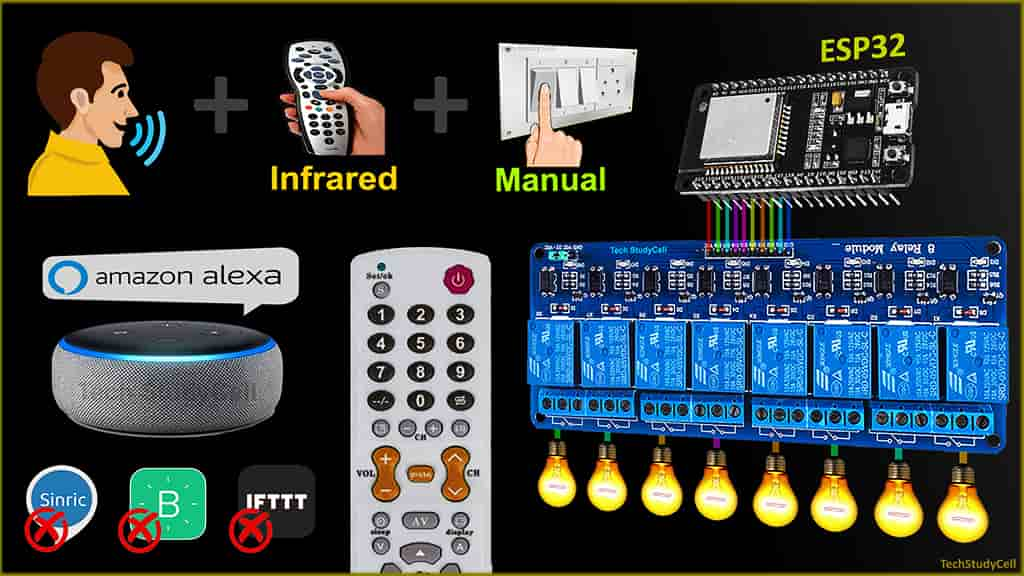
In this ESP32 project, I have explained how to make a simple ESP32 Home Automation using Alexa, IR Remote, and Manual switch to control 8 relays with and without the internet. With this IoT project, you can control 8 home appliances with voice commands, IR remote, and manual switches. If there is no internet available still you can control the relay module manually from the IR remote and switches.

With this IoT-based home automation system, if the ESP32 is connected with Wi-Fi, you can also monitor the real-time feedbacks of the relays in the Amazon Alexa App. If the Wi-Fi is available, the ESP32 will automatically connect with the Wi-Fi and the blue LED will turn on.
Table of Contents
Circuit of the IoT projects using ESP32 Alexa

The circuit is very simple, I have used D23, D22, D21, D19, D18, D5, D25 & D26 GPIO pins to control the 8-channel relay module.
And the GPIO D13, D12, D14, D27, D33, D32, D15 & D4 are connected with switches to control the relay module manually.
The output pin of the IR receiver (1838) is connected with the D35 pin of the ESP32.
I have used the INPUT_PULLUP function in Arduino IDE instead of using the pull-up resistors with each switch.
As per the source code, when the control pins of the relay module receive LOW signal the relay will turn on and the relay will turn off for the HIGH signal in the control pin.
I have used a 5V 5Amp mobile charger to supply the circuit.

If you want to use push buttons (momentary switch), then you have to connect the push buttons across the GPIO pins and GND pin as shown in the above circuit.
Required Components for the Home Automation using Alexa

- ESP32 DEV KIT V1 Amazon
- 8-channel 5V SPDT Relay Module Amazon
- TSOP1838 IR receiver (with metallic casing) Amazon
- Switches or Push Buttons Amazon
- Amazon Echo Dot or any other Alexa devices Amazon
- Any IR Remote
Affiliate Purchase Links:
Tutorial video on ESP32 Home Automation using Blynk
In the tutorial video, I have covered the following topics in detail.
- Control 8-channel relay module from Alexa, IR Remote, and Switches.
- How to get IR codes (HEX codes) from a remote.
- Program the ESP32 with the Arduino IDE.
- Set up Amazon Alexa App to connect ESP32.
- Connect home appliances with the relay module.
Important points for the ESP32 internet of things project:
- The IR receiver sensor must have a metallic casing. Otherwise, you may face issues while trying to get the Hex code.
- You need an Amazon Echo Dot or any other Alexa devices for this project.
- The ESP32 and the Echo Dot should be connected with the same Wi-Fi network.
- If you face any issues related to the Espalexa library, then please Click Here.
- Use a stable 5V 5A DC power supply.
Program ESP32 with Arduino IDE
In the Tutorial video, I have explained all the steps to program the ESP32 DEV KIT V1 using Arduino IDE.
- Update the Preferences –> Aditional boards Manager URLs: https://dl.espressif.com/dl/package_esp32_index.json, http://arduino.esp8266.com/stable/package_esp8266com_index.json
- Then install the ESP32 board from the Board manager or Click Here to download the ESP32 board.
- Download the required libraries from the following links:
- Espalexa Library: Click Here
- AceButton Library: Click Here
- IRremote Library: Click Here

**Please download the latest version of the libraries from the given links. Then install the libraries at Arduino IDE – Sketch – Include Library – Add Zip Library.
Download the Codes for this ESP32 Alexa Smart Home
First, we have to upload the Code for Getting HEX codes to ESP32 and connect the IR receiver with GPIO-35
#include <IRremote.h>

int IR_RECV_PIN = 35;

IRrecv irrecv(IR_RECV_PIN);
decode_results results;

void setup()
{
  Serial.begin(9600);
  irrecv.enableIRIn(); // Start the receiver
}

void loop()
{
  if (irrecv.decode(&results))
  {
  Serial.println(results.value, HEX); //print the HEX code
  irrecv.resume();
  }
}
After that, open the serial monitor, select the Baud Rate at 9600.
Now, you have to press all the remote buttons (one by one) which you want to use to control the relays.
Now, save all the HEX codes. You have modify the main code with these HEX codes.
Modify the main code for this ESP32 Alexa project
Now, open the main code in Arduino IDE.
Enter the Wi-Fi credential in the code:
// WiFi Credentials
const char* ssid = "WIFI NAME";
const char* password = "WIFI PASSWORD";- WiFi Name at “WiFi Name“
- WiFi Password at “WiFi Password”
Enter the Devices Name as per your requirement in the code:
// device names
String Device_1_Name = "Study Lamp";
String Device_2_Name = "CFL";
String Device_3_Name = "Yellow light";
String Device_4_Name = "Night Lamp";
String Device_5_Name = "Studio Light";
String Device_6_Name = "Outdoor Light";
String Device_7_Name = "Kitchen Light";
String Device_8_Name = "Room Light";
Alexa will identify the devices with these names. So enter the name accordingly.
case 0x80BF49B6:  relayOnOff(1);  break;
case 0x80BFC936:  relayOnOff(2);  break;
case 0x80BF33CC:  relayOnOff(3);  break;
case 0x80BF718E:  relayOnOff(4);  break;
case 0x80BFF10E:  relayOnOff(5);  break;
case 0x80BF13EC:  relayOnOff(6);  break;
case 0x80BF51AE:  relayOnOff(7);  break;
case 0x80BFD12E:  relayOnOff(8);  break;
For this ESP32 project, you need 9 HEX codes.
Copy paste the HEX code after 0x [Ex: 0x[your HEX code]].
After doing these changes, go to Tools and select the board as “DOIT ESP32 DEVKIT V1” and the proper PORT in Arduino IDE.
Then click on the upload button to program the ESP32 board.
After uploading the code, if the ESP32 connect with internet, the blue LED should turn on.
Set up Amazon Alexa App to add devices

In the tutorial video, I have explained all the steps to add devices in Amazon Alexa App.
While doing the setup of the Amazon Alexa App, the ESP32, Amazon Echo dot, and the smartphone should be connected to same the wifi network.
- Open the Amazon Alexa App. Goto on Devices and tap on the “+” icon.
- Tap on Light. In Light select other.
- Tap on DISCOVER DEVICES. This process may take 1 minute.
- Now again tap on Devices to see all connected devices.
Once the Alexa App found all the devices, you can control those devices with voice command using Alexa echo dot.

You may face No new devices found error while adding the devices with Alexa.
Then restart the echo dot, after restart once the echo dot connects with the same WiFi, tap on “Try discovery again“.
Connect Home Appliances with Relay Module

Connect the home appliances with the relay module as per the circuit diagram.
Please take proper safety precaution, while working with high voltage.
Now, turn on the 5V DC supply and 110V/220V AC supply.
Alexa Control Relay using ESP32

If the ESP32 is connected with Wi-Fi, then you can control the relay module with voice commands and Alexa App.
You can also monitor the real-time feedback in the Amazon Alexa app.
ESP32 Control Relay with IR Remote

You can always control the appliances with the IR remote. If the ESP32 connected to the internet, you can monitor the real-time feedback in the Amazon Alexa app.
So if the internet is not available, still you can control the appliances with IR remote.
Control Relays with Switches or Push Buttons

You can also manually control the appliances from the switches.
Here, whenever you press the switch, the current state of the respective relay changes. So there is no specific OFF or ON position. To turn on or off the appliance just press the respective switch.
PCB for the ESP32 Projects

To give the project a professional look and make the circuit compact, I have designed a PCB for this ESP32 IoT-based home automation project.
Components Required for PCB
- Relays 5v (SPDT) (8 no)
- BC547 Transistors (8 no)
- PC817 Optocuplors (8 no)
- 510-ohm 0.25-watt Resistor (8 no) (R1-R8)
- 1k 0.25-watt Resistors (10 no) (R9-R18)
- LED 5-mm (10 no)
- 1N4007 Diodes (8 no) (D1-D8)
- Push Buttons (8 no)
- Terminal Connectors
- 5V DC supply

Control relays with Alexa 
Control relays with IR Remote
I hope you like this Smart house IoT projects idea with the Espressif ESP32.
Click Here for more such ESP32 projects.
Please do share your feedback on this IoT project. Thank you for your time.


