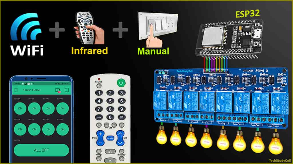
In this IoT project, I have explained how to make a simple ESP32 IoT Home Automation using Blynk & IR Remote to control 8 relays with and without the internet. With this ESP32 project, you can control 8 home appliances from the smartphone, IR remote, and manual switches. If there is no internet available still you can control the relay module from the IR remote and manual switches.

With this IoT-based smart home system, if the ESP32 connected with Wi-Fi then you can also monitor the real-time feedbacks of the relays in the Blynk App. If the Wi-Fi is available, the ESP32 will automatically connect with the Wi-Fi and the blue LED will turn on.
Table of Contents
Circuit of the IoT projects using ESP32

The circuit is very simple, I have used D23, D22, D21, D19, D18, D5, D25 & D26 GPIO to control the 8-channel relay module.
And the GPIO D13, D12, D14, D27, D33, D32, D15 & D4 connected with switches to control the relay module manually.
The output pin of the IR receiver is connected with D35.
I have used the INPUT_PULLUP function in Arduino IDE instead of using the pull-up resistors with each switch.
As per the source code, when the control pins of the relay module receive LOW signal the relay will turn on and the relay will turn off for the HIGH signal in the control pin.
I have used a 5V 5Amp mobile charger to supply the circuit.

If you want to use push buttons instead of switches, then you have to connect the push buttons across the GPIO pins and GND pin as shown in the above circuit.
Required Components for the ESP32 IoT projects

- ESP32 DEV KIT V1
- 8-channel 5V SPDT Relay Module
- TSOP1838 IR receiver (with metallic casing)
- Switches or Push Buttons
- Any IR Remote
Affiliate Purchase Links:
Tutorial video on ESP32 Home Automation using Blynk
In the tutorial video, I have covered the following topics in detail.
- Control 8-channel relay module from Blynk, IR Remote, and Switches.
- Configure Blynk App for the ESP32 IoT projects.
- How to get the HEX codes from IR Remote buttons.
- Program the ESP32 with the Arduino IDE.
- Connect home appliances with the 8-channel relay module.
Set up the Blynk App for ESP32 IoT Projects

1. Download & install the Blynk App from Google play store or App store. Then sign up.
2. Create a new project in the Blynk app. Enter the project name and choose the device as “ESP32 Dev Board“. The connection type will be Wi-Fi. Then tap on Create.
3. After that Blynk will send an Auth Token to the registered email id. The Auth Token will be required while programming the ESP32. Now, tap on OK.
Adding Button widgets in Blynk App

Now to control the 8-channel relay module you have to add 9 button widgets in the Blynk app
Steps to add buttons in the Blynk App:
- Open the project in the Blynk App Click on the “+” icon on the top. select the Button.
- Tap on that button and select the output pin –> V1 & Mode –> Switch. You can also give any name to that button. Here, I have used an active low Relay module, so to turn ON the relay we have to send “0” and “1” to turn OFF the relay.
- In a similar way create buttons with V2, V3, V4, V5, V6, V7, V8 pins to control the second, third, fourth, fifth, sixth, seventh & eighth relays.
- For the last button (ninth button), select the PIN -> V9 & Mode -> PUSH. We will use this button to turn off all the relays.
Please refer the tutorial video to set up the Blynk App.
Program ESP32 with Arduino IDE
In the Tutorial video, I have explained all the steps to program the ESP32 DEV KIT V1 using Arduino IDE.
- Update the Preferences –> Aditional boards Manager URLs: https://dl.espressif.com/dl/package_esp32_index.json, http://arduino.esp8266.com/stable/package_esp8266com_index.json
- Then install the ESP32 board from the Board manager or Click Here to download the ESP32 board.

- Install the Blynk library from Include Library or Click Here to download.
- Install the IRremote library from Include Library or Click Here to download.
- Install the AceButton library from Include Library or Click Here to download.
If you use push-button, then the AceButton library is not required.
Download the Codes for this ESP32 IoT Projects
First, we have to upload the Code for Getting HEX codes to ESP32 and connect the IR receiver with GPIO-35
#include <IRremote.h>

int IR_RECV_PIN = 35;

IRrecv irrecv(IR_RECV_PIN);
decode_results results;

void setup()
{
  Serial.begin(9600);
  irrecv.enableIRIn(); // Start the receiver
}

void loop()
{
  if (irrecv.decode(&results))
  {
  Serial.println(results.value, HEX); //print the HEX code
  irrecv.resume();
  }
}
After that, open the serial monitor, select the Baud Rate at 9600.
Now, you have to press all the remote buttons (one by one) which you want to use to control the relays.
Now, save all the HEX codes. You have to modify the main code with these HEX codes.
Modify the main code for this IoT project
Now, open the main code in Arduino IDE.
Enter the following Wi-Fi credential and Authentication token in the code:
#define AUTH "AUTH TOKEN"                 // Enter Auth Token.
#define WIFI_SSID "WIFI NAME"             //Enter Wifi Name
#define WIFI_PASS "WIFI PASSWORD" //Enter wifi Password- Auth Token sent by Blynk at “AUTH TOKEN“
- WiFi Name at “WiFi Name“
- WiFi Password at “WiFi Password”
case 0x80BF49B6:  relayOnOff(1);  break;
case 0x80BFC936:  relayOnOff(2);  break;
case 0x80BF33CC:  relayOnOff(3);  break;
case 0x80BF718E:  relayOnOff(4);  break;
case 0x80BFF10E:  relayOnOff(5);  break;
case 0x80BF13EC:  relayOnOff(6);  break;
case 0x80BF51AE:  relayOnOff(7);  break;
case 0x80BFD12E:  relayOnOff(8);  break;
case 0x80BF3BC4:  all_SwitchOff(); break;
For this ESP32 project, you need 9 HEX codes.
Copy paste the HEX code after 0x [Ex: 0x[your HEX code]].
After doing these changes, go to Tools and select the board as “DOIT ESP32 DEVKIT V1” and the proper PORT in Arduino IDE.
Then click on the upload button to program the ESP32 board.
Connect Home Appliances with Relay Module

Connect the home appliances with the relay module as per the circuit diagram.
Please take proper safety precautions, while working with high voltage.
Now, turn on the 5V DC supply and 110V/220V AC supply.
ESP32 Control Relay with Blynk App

If the ESP32 is connected with Wi-Fi, then you can control the relay module with Blynk App. You can control, monitor the current status of the relays from anywhere in the world from the Blynk App.
When the internet comes back, the ESP32 will fetch the previous state of the switches from the Blynk IoT server and accordingly turn on and off the relays.
ESP32 Control Relay with IR Remote

Control Relays with IR Remote 
Control Relays with IR Remote (No WiFi)
You can always control the appliances from the IR remote. If the ESP32 connected with Wi-Fi then it will send real-time feedback to the Blynk server.
Control Relays with Switches or Push Buttons

You can also manually control the appliances from the switches. If the ESP32 connected with Wi-Fi then it will send real-time feedback to the Blynk server.
PCB for the ESP32 Projects

To give the project a professional look and make the circuit compact, I have designed a PCB for this ESP32 IoT-based home automation project.
Solder the Components on PCB

Solder all the components as mentioned on the PCB.
Components Required for PCB
- Relays 5v (SPDT) (8 no)
- BC547 Transistors (8 no)
- PC817 Optocuplors (8 no)
- 510-ohm 0.25-watt Resistor (8 no) (R1-R8)
- 1k 0.25-watt Resistors (10 no) (R9-R18)
- LED 5-mm (10 no)
- 1N4007 Diodes (8 no) (D1-D8)
- Push Buttons (8 no)
- Terminal Connectors
- 5V DC supply

I hope you like this Smart house IoT projects idea with the Espressif ESP32.
Click Here for more such ESP32 projects.
Please do share your feedback on this IoT project. Thank you for your time.


