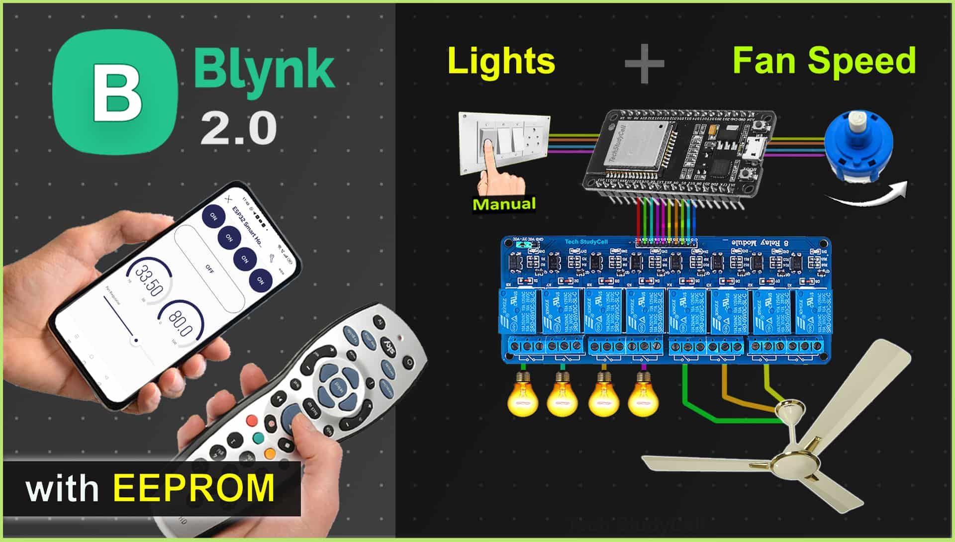
In this IoT project, I have explained how to make a practical home automation system with fan speed control using ESP32, sensors, and the New Blynk IoT platform.
With this ESP32 project, you can also control appliances, and fan speed without internet from IR remote and manual switches.

The ESP32 will automatically connect with the Blynk IoT cloud if the WiFi is available. Then you can control the lights and fan speed from anywhere in the world through the internet and monitor the real-time feedback in Blynk IoT App.
I have used all the FREE tools for this ESP32 home automation project using Blynk IoT.
So if you follow all the steps, you can easily make this Smart Home System with ESP32 and Blynk app.
Table of Contents
Required Components for the ESP32 IoT project

- ESP32 DevKIT V1 Amazon
- 4-channel 5V SPDT Relay Module Amazon
- DHT11 Sensor Amazon
- TSOP1838 IR Receiver (with metallic case) Amazon
- Switches or Pushbuttons Amazon
- Any IR Remote
- 4-step Fan Regulator OR (2.2uf & 3.3uf 250V Capacitor, 2.2-ohm 1/2W Resistors, 220k 1/4W Resistors, and 4-step selector switch)
Circuit of the ESP32 Home Automation System

The circuit is very simple, I have used D23, D22, D21 & D19 GPIO to control the first 4 relays. And D18, D5 & D25 control the next 3 relays to control the fan speed.
GPIO D13, D12, D14 & D27 are connected with switches, and GPIO D33, D32, D15 & D4 are connected with a 4-step selector switch to control the relay module manually.
I have used the INPUT_PULLUP function in Arduino IDE instead of using the pull-up resistors with each push button.
As per the source code, when the control pins of the relay module receive a LOW signal the relay will turn on and the relay will turn off for the HIGH signal in the control pin.
IR remote receiver (TSOP1838) connected with D35. And the DHT11 sensor is connected to RX2 (GPIO16).
If you want to use the pushbuttons instead of latched switches, then just connect the pushbuttons instead of the latched switches across GPIO pins and GND.

I have used a 5V 5Amp mobile charger to supply the circuit.
Please take proper safety precautions while connecting the AC appliances.
Tutorial video on Blynk ESP32 Home Automation System
In the Internet of things tutorial video, I have covered the following steps in detail.
- Control appliances with Blynk & IR Remote
- Control fan speed through the internet.
- Circuit of the ESP32 IoT home automation system.
- Explained the source code of the Blynk ESP32 IoT project.
Set up Blynk IoT Cloud for the IoT-based Project
You can refer to the following article to set up the new Blynk cloud account
Getting started with New Blynk 2.0 IoT platform
Create Blynk Template
During creating the template, I selected ESP32 as the hardware and the connection type as WiFi.
Create Datastreams in Blynk Cloud

For demonstration, I have created 4 Datastreams (V1 to V4) to control 4 relays, 1 Datastream (V5) to turn off all the relays, 1 Datastream (V0) to control fan speed, and 2 Datastreams (V6 & V7) to get the DHT11 sensor readings.
Define Datastreams for Automations

Next, you have to define which Datastreams will be available in Automation actions and conditions.
Only Virtual Pin, Enumerable, and Location Datastreams are supported.
Create Web Dashboard

After that, click and drag Switch widgets according to the number of relays, 1 slider widget, and 2 level widgets for DHT11 sensors.
Then click on “Save“.
Add Device in Blynk Cloud using Template
You can refer to the following article to add a device to the Blynk cloud.
Add Device in Blynk Cloud from Template
PCB for this ESP32 IoT Project
You can download the following PCB Gerber file for this ESP32 home automation system.

Program ESP32 with Arduino IDE
For this IoT-based home automation project, I have used the Arduino IDE to program ESP32.
First update the Preferences –> Aditional boards Manager URLs: https://dl.espressif.com/dl/package_esp32_index.json, http://arduino.esp8266.com/stable/package_esp8266com_index.json
- Then install the ESP32 board from the Board manager or Click Here to download the ESP32 board.
- Download the required libraries from the following links:
Source Codes for Blynk IoT Projects with ESP32
Click on the following buttons to download the source codes for this ESP32 project.
First, you have to upload the Code for Getting HEX codes to ESP32 and connect the IR receiver with GPIO D35.

After that, open the serial monitor, and select the Baud Rate at 9600.

Now, you have to press all the remote buttons (one by one) which you want to use to control the relays.
Now, save all the HEX codes. You have to update the main code with these HEX codes. For this IoT project, you need 5 HEX codes.
Modify the main code for this IoT-based project

In the code, you have to update only the BLYNK_TEMPLATE_ID, BLYNK_DEVICE_NAME, Auth Token, WiFi Credentials, and HEX codes of the IR remote as shown in the video.
After doing these changes, go to Tools and select the board as “DOIT ESP32 DEVKIT V1” and the proper PORT in Arduino IDE.
Then click on the upload button to program the ESP32 board.
Control Fan Speed with Blynk IoT App

Control the speed of the ceiling fan from anywhere in the world from the Blynk IoT App. If the WiFi is connected, you can also monitor the real-time feedback in the Blynk.
Control Fan Speed with IR Remote & Selector Switch


You can use any IR remote to control the fan speed. I have used 2 buttons to increase and decrease the fan speed from the IR remote.
You can also use a selector switch to control the fan speed manually if the WiFi is not connected.
Control relays with the Blynk IoT, IR Remote & Switch

You can control appliances with the New Blynk IoT app from anywhere in the world through the internet.
If the ESP32 is connected to WiFi, then you can also monitor the real-time feedback and room temperature in the Blynk IoT app.

You can use any IR remote to control the appliances.
First, get the HEX codes of unused IR Remote buttons, then update the HEX codes in the code.
If the Wi-Fi is not connected, still you can control relays with the IR remote.

You can also control the appliances with manual switches or push buttons.
If the ESP32 is connected to Wi-Fi then it will send real-time feedback to the Blynk IoT server.
Add Google Assistant with Blynk using IFTTT
You can also add Google Assistant with Blynk cloud using IFTTT. In the following article, I have explained all the steps to connect Blynk with Google Assistant using the FREE IFTTT account.
Set up IFTTT to connect Blynk Project with Google Assistant
URL syntax to send web requests in New Blynk IoT platform
Syntax: https://{server_address}/external/api/update?token={token}&{pin}={value}

The server region could be found in the right bottom corner of the web interface in the Blynk account.
I hope you like this Smart home automation system idea with ESP32 and Blynk IoT app.
Click Here for more such ESP32 projects.
Please do share your feedback on this IoT project. Thank you for your time.


