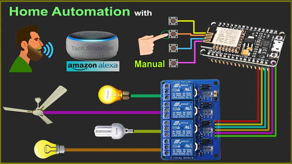
In this NodeMCU project, I have shown how to make an Alexa home automation project with manual switches using NodeMCU ESP8266, relay module, and amazon echo dot. For this ESP8266 Alexa automation project, I have only used Amazon Alexa App to control the home appliances with Alexa.

If there is no internet, still you can also control the home appliances from the push buttons and when the internet comes back the NodeMCU will automatically connect with the WiFi. It will also remember the previous state of the relay module.
For this IoT project, I have not used any third party IoT applications or any custom design PCB, so you can easily make this amazon echo home automation system at home.
Table of Contents
Circuit of ESP8266 Alexa Automation

The circuit is very simple, here I have used D1, D2, D5, D6 GPIOs to connect the relay module and the push buttons are connected with SD3, D3, D7, RX GPIO pins of NodeMCU.
I have used a 5-Volt 2-Amp mobile charger to supply this home automation system.
Required Components for this NodeMCU Project:

- NodeMCU
- 4-channel Relay Module (5V)
- Push Buttons 4nos
- Amazon Alexa Echo Dot
Tutorial video on Amazon Echo Home Automation
In this tutorial video, I have shown all the steps to make amazon echo home automation using ESP8266 NodeMCU. I have also explained how to add devices in Amazon Alexa app to control the home appliances with Alexa.

In this home automation project, I have not used any third party IoT Application like Blynk or IFTTT.
Program NodeMCU with Arduino IDE

For this Alexa home automation project, I have used the Arduino IDE to program NodeMCU.
First update the Preferences –> Aditional boards Manager URLs: https://dl.espressif.com/dl/package_esp32_index.json, http://arduino.esp8266.com/stable/package_esp8266com_index.json
Then install the ESP8266 board, I have used the 2.5.1 version, you may get issues with the latest version of ESP8266.
After that install the ESPAlexa library. Click Here to download ESPAlexa library.
Code for Alexa Home Automation
#ifdef ARDUINO_ARCH_ESP32
#include <WiFi.h>
#else
#include <ESP8266WiFi.h>
#endif
#include <Espalexa.h>
// define the GPIO connected with Relays and switches
#define RelayPin1 5  //D1
#define RelayPin2 4  //D2
#define RelayPin3 14 //D5
#define RelayPin4 12 //D6

#define SwitchPin1 10  //SD3
#define SwitchPin2 0   //D3
#define SwitchPin3 13  //D7
#define SwitchPin4 3   //RX

#define wifiLed   16   //D0

int toggleState_1 = 0; //Define integer to remember the toggle state for relay 1
int toggleState_2 = 0; //Define integer to remember the toggle state for relay 2
int toggleState_3 = 0; //Define integer to remember the toggle state for relay 3
int toggleState_4 = 0; //Define integer to remember the toggle state for relay 4

// prototypes
boolean connectWifi();
//callback functions
void firstLightChanged(uint8_t brightness);
void secondLightChanged(uint8_t brightness);
void thirdLightChanged(uint8_t brightness);
void fourthLightChanged(uint8_t brightness);

// WiFi Credentials
const char* ssid = "WiFi Name";
const char* password = "WiFi Password";

// device names
String Device_1_Name = "Study Lamp";
String Device_2_Name = "CFL";
String Device_3_Name = "Yellow light";
String Device_4_Name = "Red light";

boolean wifiConnected = false;

Espalexa espalexa;

//our callback functions
void firstLightChanged(uint8_t brightness)
{
  //Control the device
  if (brightness == 255)
    {
      digitalWrite(RelayPin1, LOW);
      Serial.println("Device1 ON");
      toggleState_1 = 1;
    }
  else
  {
    digitalWrite(RelayPin1, HIGH);
    Serial.println("Device1 OFF");
    toggleState_1 = 0;
  }
}

void secondLightChanged(uint8_t brightness)
{
  //Control the device
  if (brightness == 255)
    {
      digitalWrite(RelayPin2, LOW);
      Serial.println("Device2 ON");
      toggleState_2 = 1;
    }
  else
  {
    digitalWrite(RelayPin2, HIGH);
    Serial.println("Device2 OFF");
    toggleState_2 = 0;
  }
}

void thirdLightChanged(uint8_t brightness)
{
  //Control the device
  if (brightness == 255)
    {
      digitalWrite(RelayPin3, LOW);
      Serial.println("Device3 ON");
      toggleState_3 = 1;
    }
  else
  {
    digitalWrite(RelayPin3, HIGH);
    Serial.println("Device3 OFF");
    toggleState_3 = 0;
  }
}

void fourthLightChanged(uint8_t brightness)
{
  //Control the device
  if (brightness == 255)
    {
      digitalWrite(RelayPin4, LOW);
      Serial.println("Device4 ON");
      toggleState_4 = 1;
    }
  else
  {
    digitalWrite(RelayPin4, HIGH);
    Serial.println("Device4 OFF");
    toggleState_4 = 0;
  }
}

void relayOnOff(int relay){

    switch(relay){
      case 1:
             if(toggleState_1 == 0){
              digitalWrite(RelayPin1, LOW); // turn on relay 1
              toggleState_1 = 1;
              Serial.println("Device1 ON");
              }
             else{
              digitalWrite(RelayPin1, HIGH); // turn off relay 1
              toggleState_1 = 0;
              Serial.println("Device1 OFF");
              }
             delay(100);
      break;
      case 2:
             if(toggleState_2 == 0){
              digitalWrite(RelayPin2, LOW); // turn on relay 2
              toggleState_2 = 1;
              Serial.println("Device2 ON");
              }
             else{
              digitalWrite(RelayPin2, HIGH); // turn off relay 2
              toggleState_2 = 0;
              Serial.println("Device2 OFF");
              }
             delay(100);
      break;
      case 3:
             if(toggleState_3 == 0){
              digitalWrite(RelayPin3, LOW); // turn on relay 3
              toggleState_3 = 1;
              Serial.println("Device3 ON");
              }else{
              digitalWrite(RelayPin3, HIGH); // turn off relay 3
              toggleState_3 = 0;
              Serial.println("Device3 OFF");
              }
             delay(100);
      break;
      case 4:
             if(toggleState_4 == 0){
              digitalWrite(RelayPin4, LOW); // turn on relay 4
              toggleState_4 = 1;
              Serial.println("Device4 ON");
              }
             else{
              digitalWrite(RelayPin4, HIGH); // turn off relay 4
              toggleState_4 = 0;
              Serial.println("Device4 OFF");
              }
             delay(100);
      break;
      default : break;
      }
}
// connect to wifi – returns true if successful or false if not
boolean connectWifi()
{
  boolean state = true;
  int i = 0;

  WiFi.mode(WIFI_STA);
  WiFi.begin(ssid, password);
  Serial.println("");
  Serial.println("Connecting to WiFi");

  // Wait for connection
  Serial.print("Connecting...");
  while (WiFi.status() != WL_CONNECTED) {
    delay(500);
    Serial.print(".");
    if (i > 20) {
      state = false; break;
    }
    i++;
  }
  Serial.println("");
  if (state) {
    Serial.print("Connected to ");
    Serial.println(ssid);
    Serial.print("IP address: ");
    Serial.println(WiFi.localIP());
  }
  else {
    Serial.println("Connection failed.");
  }
  return state;
}

void addDevices(){
  // Define your devices here.
  espalexa.addDevice(Device_1_Name, firstLightChanged); //simplest definition, default state off
  espalexa.addDevice(Device_2_Name, secondLightChanged);
  espalexa.addDevice(Device_3_Name, thirdLightChanged);
  espalexa.addDevice(Device_4_Name, fourthLightChanged);
  espalexa.begin();
}
void setup()
{
  Serial.begin(115200);

  pinMode(RelayPin1, OUTPUT);
  pinMode(RelayPin2, OUTPUT);
  pinMode(RelayPin3, OUTPUT);
  pinMode(RelayPin4, OUTPUT);
  pinMode(wifiLed, OUTPUT);

  pinMode(SwitchPin1, INPUT_PULLUP);
  pinMode(SwitchPin2, INPUT_PULLUP);
  pinMode(SwitchPin3, INPUT_PULLUP);
  pinMode(SwitchPin4, INPUT_PULLUP);

  //During Starting all Relays should TURN OFF
  digitalWrite(RelayPin1, HIGH);
  digitalWrite(RelayPin2, HIGH);
  digitalWrite(RelayPin3, HIGH);
  digitalWrite(RelayPin4, HIGH);

  // Initialise wifi connection
  wifiConnected = connectWifi();

  if (wifiConnected)
  {
    addDevices();
  }
  else
  {
    Serial.println("Cannot connect to WiFi. So in Manual Mode");
    delay(1000);
  }
}

void loop()
{
   if (WiFi.status() != WL_CONNECTED)
  {
    //Serial.print("WiFi Not Connected ");
    //Serial.println(wifiConnected);
    digitalWrite(wifiLed, HIGH); //Turn off WiFi LED
    //Manual Switch Control
    if (digitalRead(SwitchPin1) == LOW){
      delay(200);
      relayOnOff(1);
    }
    else if (digitalRead(SwitchPin2) == LOW){
      delay(200);
      relayOnOff(2);
    }
    else if (digitalRead(SwitchPin3) == LOW){
      delay(200);
      relayOnOff(3);
    }
    else if (digitalRead(SwitchPin4) == LOW){
      delay(200);
      relayOnOff(4);
    }

  }
  else
  {
    //Serial.print("WiFi Connected  ");
    //Serial.println(wifiConnected);
    digitalWrite(wifiLed, LOW);
    //Manual Switch Control
    if (digitalRead(SwitchPin1) == LOW){
      delay(200);
      relayOnOff(1);
    }
    else if (digitalRead(SwitchPin2) == LOW){
      delay(200);
      relayOnOff(2);
    }
    else if (digitalRead(SwitchPin3) == LOW){
      delay(200);
      relayOnOff(3);
    }
    else if (digitalRead(SwitchPin4) == LOW){
      delay(200);
      relayOnOff(4);
    }
    //WiFi Control
    if (wifiConnected){
      espalexa.loop();
      delay(1);
    }
    else {
      wifiConnected = connectWifi(); // Initialise wifi connection
      if(wifiConnected){
      addDevices();
      }
    }
  }
}
Enter the following WiFi credential in the code:
- WiFi Name at “WiFi Name”
- WiFi Password at “WiFi Password”
Then enter the device names in the code. Alexa will identify that device with the name mentioned in the code.
Now select the board as NodeMCU 1.0 and the PORT in Arduino IDE. Then click on the upload button to program the NodeMCU board.

After uploading the code to NodeMCU, the blue LED connected with pin D0 should turn on as shown in the picture.
If the internet is not available, the blue LED will turn off. Then you can control the relay module with push buttons.
And when the internet comes back the NodeMCU will automatically connect with the WiFi and the blue LED will turn on.
Then you can control the home appliances with Alexa and the pushbuttons.
Configure Amazon Alexa App

In the tutorial video, I have explained all the steps to add devices to Amazon Alexa App.
While configuring the Amazon Alexa App, the NodeMCU or ESP8265, Amazon Echo dot, and the Mobile should be connected with same the wifi.
Once the Alexa App found all the devices, you can control those devices with voice commands using the Alexa echo dot.

You may face No new devices found error while adding the devices with Alexa.
Then restart the echo dot, after restart once the echo dot connect with the same WiFi, tap on “Try discovery again”.
Connect Home Appliances with Relay

Now, please refer the above circuit to connect 4 home appliances with relay module.
Please take proper safety precautions while working with high voltage.
Amazon Echo Home Automation system is ready

Now, the IoT project on Alexa home automation is ready, so you can control the home appliances with voice commands.
“Alexa, turn on light”, “Alexa, turn off light”, “Alexa, turn on studio light”, etc.
The NodeMCU and Echo Dot should be connected with the same wifi.
PCB for this NodeMCU Home Automation system

To make the circuit compact, I have designed a PCB for this ESP32 project.
If you want, you can also use this PCB to make the circuit compact and give the project a professional look. This PCB can be used for any ESP32 Home Automation project.

About PCBWay and their services
PCBway is a very well-known PCB manufacturer for various types of PCB boards at very affordable prices. They produce FR-4 and Aluminum boards and advanced PCBs like Rogers, HDI, Flexible and Rigid-Flex boards.
For the online instant quote page please visit – pcbway.com/orderonline
Other than a basic visual check, all boards at PCBWay pass the most stringent tests. To ensure the quality of the final product, different test and inspection equipment are used, including Flying Probe Testers, X-ray inspection machines, Automated Optical Inspection (AOI) machines, etc.
You can also explore their open source community to get different types of PCB projects with all required details pcbway.com/project/.
For more details please visit the following articles.
Why PCBway
PCB Capabilities
High-Quality PCB
Steps to order PCB from PCBWay
To order the PCB first visit their website PCBWay.com.

Then enter the following details:
- PCB Size (Length & Width) in mm & PCB quantity
- Select masking color for the PCB
- Select country and shipping method
- Click on the “Save to Cart” button

Now click on the “Add Gerber Files” to upload the PCB Gerber file.
Then click on the “Submit Order Now” to place the order.
After that, they will review the Gerber file and accordingly confirm the order.
I have used their services for my different electronics projects, I always received the PCB on time and the quality is very good in this price range.
NodeMCU Alexa Home Automation system is now ready

With the PCB, the project looks compact and professional.
I hope you like this Smart home IoT projects idea with the ESP8266 and Alexa app.
Click Here for more such smart home projects.
Please do share your feedback on this IoT project. Thank you for your time.


