Are you looking to build a smart IoT-based LED dimmer that can be controlled from your smartphone, Alexa, Google Home, or even an IR remote?
In this tutorial, we’ll build an ESP32 Smart LED Dimmer Project using ESP RainMaker, which allows cloud-based control and real-time feedback with PWM brightness control.

This project is an excellent example of how to combine ESP RainMaker IoT Cloud, PWM control, and voice assistants to create a truly smart lighting system.

This ESP32 IoT LED Dimmer lets you:
- Control LED brightness from anywhere using the ESP RainMaker app.
- Use Alexa or Google Assistant for voice commands.
- Adjust brightness manually using push buttons.
- Control the light with an IR remote.
- Get real-time feedback in all apps and platforms.
Even if the Wi-Fi disconnects, you can still manually or remotely control the brightness — making it a reliable and practical smart home project.
Table of Contents
Required Components for ESP32 Dimmer Project

- ESP32 (DOIT)
- 7805 voltage regulator with heatsink
- TIP122 NPN Transistor with heatsink
- 1k resistor (R3)
- 220 ohm resistor (R1 R2)
- 5-mm LEDs
- IR Receiver (TSOP1838)
- Push Buttons (3 qty) for Manual Control
- 100 µF (C1) and 0.1 µF (C2, C3) capacitor (Optional)
- Terminal connectors
- 12V LED strip
- 12V Power Supply
Circuit Diagram of the ESP32 LED Dimmer

The circuit uses PWM (Pulse Width Modulation) from the ESP32 to vary the LED brightness.
- PWM Output (GPIO 13) → Connected to the base of TIP122 via 1k resistor.
- Push Buttons (GPIO 22, 23, 18) → Used for ON/OFF and brightness control (using internal pull-up).
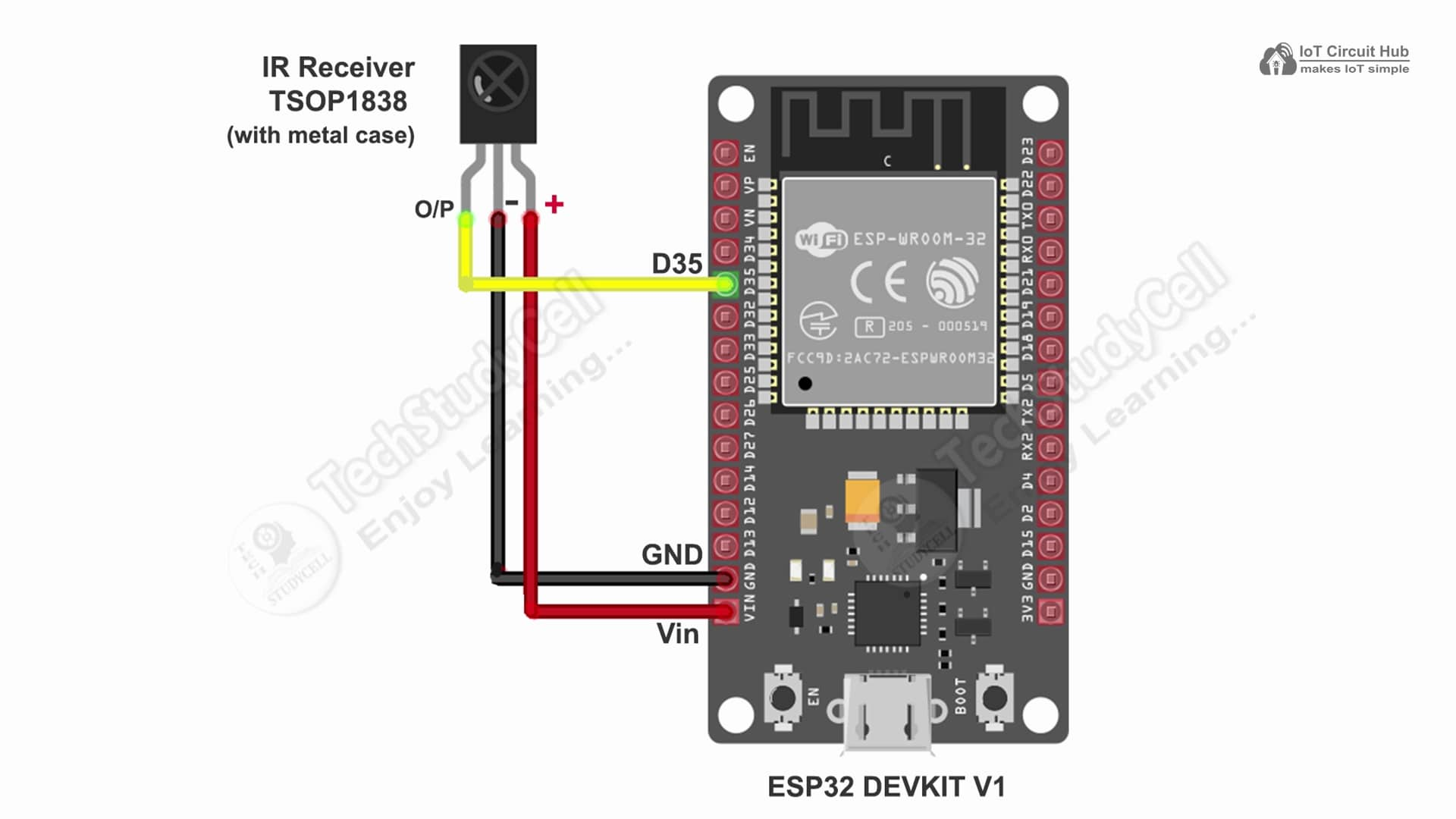
- IR Receiver (GPIO 35) → Used to receive remote commands from the IR Remote.
- 5V Regulator (7805) → Provides stable power supply for ESP32 and LED driver circuit.
- Wi-Fi LED (GPIO 2) → Indicates wi-fi connection status.
Optionally, you can connect two 0.1 µF (100 nF) ceramic capacitors (C2 & C3) across the input and output of the 7805 voltage regulator for noise filtering, and one 100 µF electrolytic capacitor (C1) across the input (12 V to GND) for voltage stabilization. Refer to the following circuit for proper placement.
Tutorial video on ESP32 LED Dimmer using ESP Rainmaker
This ESP32 project combines manual control, IR remote, and IoT integration via ESP RainMaker.
It enables LED brightness control using the RainMaker app, Alexa, Google Home, or physical buttons, with state memory and OTA updates for a complete smart lighting solution.
PCB Layout for ESP32 LED Dimmer
Please download the PCB layout, then print it on the A4 page.
Please verify the PCB size before printing; it should match the one mentioned in the Layout.
Homemade PCB for DIY ESP32 Dimmer Project

In the tutorial video, I have explained how you can easily make the complete circuit on a zero PCB using the PCB Layout.
PCB for the ESP32 LED Dimmer project
You can also download the PCB Gerber file and order the PCB from PCBWay.
About PCBWay and their services
You can order any custom-designed PCBs from PCBWay at very reasonable prices.

You can also join the global stage for innovators and makers! PCBWay invites you to participate in the 8th Project Design Contest, featuring three categories —

Electronic, Mechanical, and AIoT Projects. Showcase your creativity, share your designs, and win exciting prizes worth up to $1500 cash, developer kits, and more. Gain worldwide recognition and connect with passionate creators from across the globe.
📅 Submission Deadline: January 31, 2026
👉 Enter now: PCBWay 8th Project Design Contest
Program ESP32 with Arduino IDE
In the Tutorial video, I explained all the steps to program the ESP32 using Arduino IDE.
- Update the Preferences –> Additional boards Manager URLs: http://arduino.esp8266.com/stable/package_esp8266com_index.json,https://raw.githubusercontent.com/espressif/arduino-esp32/gh-pages/package_esp32_index.json
- Then install the ESP32 board (Version: 2.0.14) from the Board manager or Click Here to download the ESP32 board.
- Download the required libraries from the following links:
- IRremote Library (Version 4.5.0)
- In Arduino IDE, select Board as ‘ESP32 DEV Module‘, and the Partition scheme as ‘RainMaker‘.
Source Codes for ESP RainMaker ESP32 IoT Project
Click on the following buttons to download the source code for this ESP32 project.
This code is provided free for project purpose and fair use only.
Please do mail us to [email protected] if you want to use it commercially.
Copyrighted © by Tech StudyCell
First, you have to upload the Code for Getting HEX codes to ESP32 and connect the IR receiver with GPIO D35.


After that, open the serial monitor and select the Baud Rate at 115200.
Now, you have to press all the remote buttons (one by one) which you want to use to control the relays.
Now, save all the HEX codes. You have to update the main code with these HEX codes. You need 3 HEX codes for this IoT Project.
In the main sketch, update the HEX code of the IR Remote buttons (as shown in the tutorial video).
// ======= IR Remote Custom Codes (update as needed) =======
#define IR_POWER_CODE   0x6996F300
#define IR_DOWN_CODE    0x6897F300
#define IR_UP_CODE      0x718EF300
Here, I have given the name “Window LED“. If you want you can also change the device names. Google and Alexa will identify the devices with this name.
static Device dimmer_device("Window LED", ESP_RMAKER_DEVICE_LIGHT, &gpio_pwm);In the code, I have used Preferences.h library to remember the last states of all the GPIO connected with relays. Please refer to the following article on the ESP32 Preferences library.
Below is a paragraph-by-paragraph explanation for every major code block, describing exactly what each section does and how it contributes to the project.
Header Files
#include "RMaker.h"
#include "WiFi.h"
#include "WiFiProv.h"
#include <IRremote.hpp>   // v4.5.0
#include <Preferences.h>
This section includes all the necessary libraries for the project.
- RMaker.h provides access to the ESP RainMaker cloud platform, enabling control via mobile apps, Alexa, and Google Home.
- WiFi.h handles Wi-Fi connectivity for the ESP32.
- WiFiProv.h enables Wi-Fi provisioning via BLE or SoftAP using the RainMaker app.
- IRremote.hpp allows the ESP32 to receive and decode signals from an IR remote (version 4.5.0).
- Preferences.h is used for saving and restoring settings like brightness and power state in non-volatile flash memory.
Hardware Pin Definitions
#define PWM_PIN         13
#define WIFI_LED        2
#define BUTTON_UP       18
#define BUTTON_DOWN     22
#define BUTTON_POWER    23
#define BUTTON_BOOT     0
#define IR_RECV_PIN     33
These #define statements assign descriptive names to ESP32 GPIO pins.
- PWM_PIN (13): Controls the LED brightness via PWM.
- WIFI_LED (2): Indicates Wi-Fi connection status.
- BUTTON_UP, BUTTON_DOWN, BUTTON_POWER: Used for manual brightness and power control.
- BUTTON_BOOT (0): Used to reset Wi-Fi or factory settings.
- IR_RECV_PIN (33): Connects to the IR receiver module to read remote control signals.
Configuration Settings
#define DEFAULT_POWER_MODE true
#define DEFAULT_DIMMER_LEVEL 50
#define BRIGHTNESS_STEP 10
#define MAX_BRIGHTNESS 100
#define MIN_BRIGHTNESS 0
These constants define default operating behavior and constraints:
- The dimmer starts in the ON state with 50% brightness.
- Each press of the UP/DOWN button changes brightness by 10%.
- Brightness levels are limited between 0% and 100%.
RainMaker Provisioning Setup
const char *service_name = "PROV_Dimmer1";
const char *pop = "dimmer1234";
These are credentials for ESP RainMaker provisioning.
- service_name is the device’s unique name visible during BLE/SoftAP setup.
- pop (Proof of Possession) ensures secure pairing between the device and mobile app.
Global Variables and Device Declaration
bool dimmer_state = DEFAULT_POWER_MODE;
int dimmer_level = DEFAULT_DIMMER_LEVEL;
bool wifi_connected = false;

static int gpio_pwm = PWM_PIN;
static Device dimmer_device("Window LED", ESP_RMAKER_DEVICE_LIGHT, &gpio_pwm);
Param brightness_param("Brightness", ESP_RMAKER_PARAM_BRIGHTNESS,
                       value(DEFAULT_DIMMER_LEVEL),
                       PROP_FLAG_READ | PROP_FLAG_WRITE);

Preferences prefs;
Here, we declare global variables to store the LED’s power state, brightness level, and Wi-Fi status.
- The Device object (
dimmer_device) defines a virtual “Window LED” device in RainMaker. - The Param object (
brightness_param) adds a brightness slider to the RainMaker dashboard and allows remote adjustments. - The Preferences object (
prefs) is used for reading and writing settings to non-volatile flash memory.
IR Remote Custom Codes
#define IR_POWER_CODE   0x6996F300
#define IR_DOWN_CODE    0x6897F300
#define IR_UP_CODE      0x718EF300
These hexadecimal codes represent the IR signals for power toggle, brightness down, and brightness up buttons.
Each remote sends unique codes — you can customize these based on your IR remote model by checking the serial output.
Function Prototypes
void applyPWM();
void updateRainMaker();
void saveState();
These are forward declarations of key functions used later in the code:
- applyPWM() adjusts LED brightness.
- updateRainMaker() syncs device state with the cloud.
- saveState() stores the latest power and brightness settings in memory.
Provisioning Event Handler
void sysProvEvent(arduino_event_t *sys_event) {
  switch (sys_event->event_id) {
    case ARDUINO_EVENT_PROV_START:
#if CONFIG_IDF_TARGET_ESP32S2
      printQR(service_name, pop, "softap");
#else
      printQR(service_name, pop, "ble");
#endif
      Serial.println("\nScan the QR code or copy the link above to provision the device.");
      break;
  }
}
This function handles ESP RainMaker provisioning events.
When provisioning begins, the ESP32 prints a QR code or link on the serial monitor. You can scan this with the RainMaker app to connect your ESP32 to Wi-Fi using BLE (default) or SoftAP (ESP32-S2).
Wi-Fi Event Handler
void WiFiEvent(arduino_event_t *event) {
  switch (event->event_id) {
    case ARDUINO_EVENT_WIFI_STA_CONNECTED:
      Serial.println("Wi-Fi connected ✅");
      wifi_connected = true;
      digitalWrite(WIFI_LED, HIGH);
      break;

    case ARDUINO_EVENT_WIFI_STA_DISCONNECTED:
      Serial.println("Wi-Fi lost ❌, retrying...");
      wifi_connected = false;
      digitalWrite(WIFI_LED, LOW);
      WiFi.reconnect();
      break;
  }
}
This function monitors Wi-Fi status:
- When connected, it prints a success message and turns the Wi-Fi LED ON.
- When disconnected, it turns the LED OFF and automatically tries to reconnect.
RainMaker Write Callback
void write_callback(Device *device, Param *param, const param_val_t val,
                    void *priv_data, write_ctx_t *ctx) {
  const char *param_name = param->getParamName();

  if (strcmp(param_name, ESP_RMAKER_DEF_POWER_NAME) == 0) {
    dimmer_state = val.val.b;
    Serial.printf("Power set to: %s\n", dimmer_state ? "ON" : "OFF");
  }
  else if (strcmp(param_name, "Brightness") == 0) {
    dimmer_level = val.val.i;
    Serial.printf("Brightness set via RainMaker: %d%%\n", dimmer_level);
  }

  applyPWM();
  saveState();
  param->updateAndReport(val);
}
This callback function executes when the RainMaker app, Alexa, or Google Home sends a command.
It checks which parameter was changed — Power or Brightness — then updates the variables, applies PWM changes to the LED, saves the state to memory, and reports the updated status back to RainMaker.
Apply PWM Function
void applyPWM() {
  int pwmValue = (dimmer_state) ? map(dimmer_level, 0, 100, 0, 255) : 0;
  ledcWrite(0, pwmValue);
}
This function converts brightness percentage (0–100%) into a PWM duty cycle (0–255) and sends it to the LED.
If the light is OFF, it sets PWM to 0. The LEDC (LED Control) module on the ESP32 generates a stable PWM signal suitable for LED dimming.
Save State Function
void saveState() {
  prefs.begin("dimmer", false);
  prefs.putBool("power", dimmer_state);
  prefs.putInt("level", dimmer_level);
  prefs.end();
  Serial.println("State saved to flash ✅");
}
This function stores the latest power and brightness levels into ESP32’s non-volatile flash memory.
This ensures the LED resumes with the same settings even after a power cycle.
Update RainMaker Function
void updateRainMaker() {
  if (wifi_connected) {
    dimmer_device.updateAndReportParam(ESP_RMAKER_DEF_POWER_NAME, dimmer_state);
    dimmer_device.updateAndReportParam("Brightness", dimmer_level);
  }
}
It sends the latest power and brightness values to the RainMaker cloud only when Wi-Fi is connected.
This keeps the RainMaker app, Alexa, and Google Home perfectly in sync with the physical device.
Setup Function
void setup() {
  Serial.begin(115200);
  delay(1000);

  // Pin setup
  pinMode(WIFI_LED, OUTPUT);
  pinMode(BUTTON_UP, INPUT_PULLUP);
  pinMode(BUTTON_DOWN, INPUT_PULLUP);
  pinMode(BUTTON_POWER, INPUT_PULLUP);
  pinMode(BUTTON_BOOT, INPUT);
  digitalWrite(WIFI_LED, LOW);

  // PWM setup
  ledcSetup(0, 5000, 8);
  ledcAttachPin(PWM_PIN, 0);

  // IR setup
  IrReceiver.begin(IR_RECV_PIN, ENABLE_LED_FEEDBACK);
  Serial.println("IR Receiver ready...");
The setup initializes all peripherals.
Serial communication starts, GPIO pins are configured, and the PWM channel is initialized at 5 kHz, 8-bit resolution.
The IR receiver is also activated, ready to decode incoming remote signals.
  // Load last state
  prefs.begin("dimmer", true);
  dimmer_state = prefs.getBool("power", DEFAULT_POWER_MODE);
  dimmer_level = prefs.getInt("level", DEFAULT_DIMMER_LEVEL);
  prefs.end();
  Serial.printf("Restored -> Power: %s, Brightness: %d%%\n",
                dimmer_state ? "ON" : "OFF", dimmer_level);

  applyPWM();
This part loads the previously saved brightness and power state from flash memory.
After reading the values, it immediately applies them to restore the LED’s last known state.
  // RainMaker setup
  Node my_node = RMaker.initNode("ESP32 PWM LED Dimmer");

  dimmer_device.addNameParam();
  dimmer_device.addPowerParam(dimmer_state);
  brightness_param.addBounds(value(0), value(100), value(1));
  brightness_param.addUIType(ESP_RMAKER_UI_SLIDER);
  dimmer_device.addParam(brightness_param);
  dimmer_device.assignPrimaryParam(dimmer_device.getParamByName(ESP_RMAKER_DEF_POWER_NAME));
  dimmer_device.addCb(write_callback);

  my_node.addDevice(dimmer_device);

  RMaker.enableOTA(OTA_USING_PARAMS);
  RMaker.enableTZService();
  RMaker.enableSchedule();
  RMaker.start();
This section initializes the ESP RainMaker node and registers the device parameters — Power and Brightness — with slider control.
The device also supports Over-the-Air (OTA) firmware updates, time zone services, and scheduling from the app.
Finally, RainMaker services are started, connecting the ESP32 to the cloud.
  WiFi.onEvent(sysProvEvent);
  WiFi.onEvent(WiFiEvent);

#if CONFIG_IDF_TARGET_ESP32S2
  WiFiProv.beginProvision(WIFI_PROV_SCHEME_SOFTAP, WIFI_PROV_SCHEME_HANDLER_NONE,
                          WIFI_PROV_SECURITY_1, pop, service_name);
#else
  WiFiProv.beginProvision(WIFI_PROV_SCHEME_BLE, WIFI_PROV_SCHEME_HANDLER_NONE,
                          WIFI_PROV_SECURITY_1, pop, service_name);
#endif

  Serial.println("Setup complete. Waiting for provisioning...");
}
Here, the ESP32 begins Wi-Fi provisioning via BLE or SoftAP depending on the board.
Users can connect to the device using the RainMaker mobile app to set up Wi-Fi credentials and register it to their account.
Loop Function
void loop() {
  static unsigned long lastPress = 0;
  unsigned long now = millis();
The loop continuously monitors button inputs, IR signals, and reset events.
A debounce mechanism ensures button presses are registered only every 250 ms.
  // --- Manual Buttons ---
  if (now - lastPress > 250) {
    if (digitalRead(BUTTON_UP) == LOW) {
      dimmer_level = min(dimmer_level + BRIGHTNESS_STEP, MAX_BRIGHTNESS);
      Serial.printf("Brightness Up: %d%%\n", dimmer_level);
      applyPWM(); saveState(); updateRainMaker();
      lastPress = now;
    }
    else if (digitalRead(BUTTON_DOWN) == LOW) {
      dimmer_level = max(dimmer_level - BRIGHTNESS_STEP, MIN_BRIGHTNESS);
      Serial.printf("Brightness Down: %d%%\n", dimmer_level);
      applyPWM(); saveState(); updateRainMaker();
      lastPress = now;
    }
    else if (digitalRead(BUTTON_POWER) == LOW) {
      dimmer_state = !dimmer_state;
      Serial.printf("Power toggled: %s\n", dimmer_state ? "ON" : "OFF");
      applyPWM(); saveState(); updateRainMaker();
      lastPress = now;
    }
  }
This section handles manual button control:
- The UP and DOWN buttons adjust brightness in 10% steps.
- The POWER button toggles the LED ON or OFF.
After each action, the changes are saved and synced with the RainMaker cloud.
  // --- IR Remote ---
  if (IrReceiver.decode()) {
    uint32_t code = IrReceiver.decodedIRData.decodedRawData;
    Serial.printf("IR Code: 0x%lX\n", code);

    if (code == IR_POWER_CODE) {
      dimmer_state = !dimmer_state;
    } else if (code == IR_UP_CODE) {
      dimmer_level = min(dimmer_level + BRIGHTNESS_STEP, MAX_BRIGHTNESS);
    } else if (code == IR_DOWN_CODE) {
      dimmer_level = max(dimmer_level - BRIGHTNESS_STEP, MIN_BRIGHTNESS);
    }

    applyPWM(); saveState(); updateRainMaker();
    IrReceiver.resume();
  }
Here, the ESP32 reads and decodes incoming IR remote signals.
Depending on the received code, it toggles power or changes brightness.
After processing, the IR receiver resumes listening for new commands.
  // --- Boot Button (Reset Handling) ---
  if (digitalRead(BUTTON_BOOT) == LOW) {
    delay(100);
    int startTime = millis();
    while (digitalRead(BUTTON_BOOT) == LOW) delay(50);
    int elapsed = millis() - startTime;

    if (elapsed > 10000) {
      Serial.println("Factory Reset Triggered!");
      RMakerFactoryReset(2);
    } else if (elapsed > 3000) {
      Serial.println("Wi-Fi Reset Triggered!");
      RMakerWiFiReset(2);
    }
  }

  delay(100);
}
This final section allows device reset using the BOOT button:
- Press and hold for 3–10 seconds to reset Wi-Fi credentials only.
- Hold for over 10 seconds to perform a full factory reset, erasing all stored data and unlinking the device from RainMaker.
Setting Up ESP RainMaker
ESP RainMaker is Espressif’s free IoT platform for ESP32 that allows you to connect your project to the cloud and control it using the ESP RainMaker mobile app.
It also supports integration with Alexa and Google Home.
🧩 Steps:
- Install the ESP RainMaker app (available on Android & iOS).
- Log in using your Espressif ID or Google account.
- Power up the ESP32 — it will start BLE provisioning mode.
- Press and hold the BOOT button for 10 seconds.
- Turn on the mobile Bluetooth and GPS.
- Scan the QR code from the Serial Monitor.
- Connect to your Wi-Fi through the app.
Once the setup is done, the device will appear on your dashboard, allowing you to control the LED’s brightness directly.
Please refer to the following article to add the devices to the ESP RainMaker app.
Now, please refer to the following articles to connect the ESP RainMaker with Amazon Alexa and Google Home App.
After doing all these steps, now you control the appliances with Google Assistant and Alexa.


Working Principle
The ESP32 generates a PWM signal to control the LED brightness.
Here’s how each control method works:
- ESP RainMaker App: Adjust brightness using the slider; the app sends commands to ESP32 via the cloud.
- Alexa / Google Home: You can use voice commands like: “Alexa, set LED brightness to 50%”
“Hey Google, dim the light to 30%” - Manual Switch: Push buttons can toggle power or adjust brightness locally.
- IR Remote: Change brightness or power state with any standard IR remote.
All these methods are synchronized — when brightness changes manually or via IR, the updated state is sent to the cloud, so your RainMaker app always shows the correct value.
The ESP32 saves the last brightness level and power state in EEPROM.
So even after a power cut or reboot, the light returns to the previous state — giving it a smart memory function.
I hope you like this ESP32 IoT project.
Click Here for more such ESP32 projects.
Please do share your feedback.


