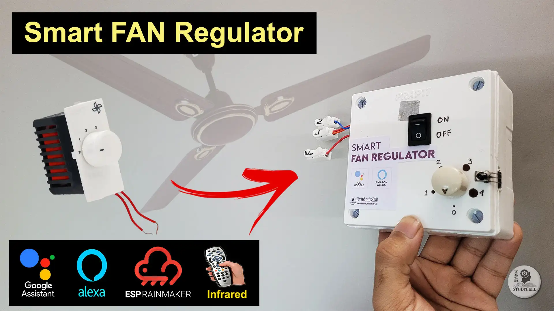
In this project, you’ll learn how to build an ESP32 Fan Speed Control system that lets you control your ceiling fan using Wi-Fi, Alexa, Google Home, and even an IR remote or manual switch.


This IoT Smart Fan Regulator uses a capacitor-based AC dimmer circuit and the ESP RainMaker cloud platform, allowing smooth, silent, and energy-efficient fan speed control through both voice commands and a mobile app.
Table of Contents
Tutorial video on ESP32 Fan Speed Control Project
Features of ESP32 Fan Speed Control Project
- Control fan speed from anywhere using the ESP RainMaker App.
- Alexa and Google Home integration for voice control.
- Four fan speed levels (0–4) with real-time cloud feedback.
- IR remote and manual switch operation when offline.
- Uses capacitor-based dimmer for quiet fan speed regulation.
- Automatically remembers last speed and power state.
- Supports OTA updates, Wi-Fi provisioning, and ESP RainMaker.

The ESP32 controls three relays connected to capacitors that change the voltage supplied to the fan motor. The fan speed is adjusted through capacitive reactance, providing four precise speed levels without generating noise or heat.
You can set the speed using:
- The RainMaker app slider (0 to 4 steps)
- Voice commands via Alexa or Google Home
- IR remote buttons
- Manual selector switches
All controls stay synchronized with the ESP RainMaker cloud, so the app always shows the correct fan status in real time.
Required Components for ESP32 AC Dimmer Project

- ESP32 Devkit.
- 4-channel 5V SPDT Relay Module.
- TSOP1838 IR Receiver
- 4-step Fan Regulator (capacitor-based)
- AC to DC converter (5V)
- Switch (latched)
- Connecting wires
💡 Note:
If you already have a 4-step capacitor fan regulator, you can simply remove the selector switch and connect the capacitor–resistor dimming circuit directly through the relays for automatic fan speed control.

However, if you don’t have one, you can build the AC dimming circuit manually using two capacitors (3.3µF and 2.2µF, 440V AC-rated), two 2.2Ω ½W resistors, two 220kΩ ¼W resistors, and a 4-step rotary selector switch, as shown in the following circuit diagram.
Circuit Diagram of the ESP32 Fan Regulator

In this ESP32 Fan Speed Control project, the circuit is designed around an ESP32 board that manages three relays, four manual selector switches, one power toggle switch, a Wi-Fi status LED (in-built LED), and an IR receiver.
The ESP32 controls three relays that switch between different capacitor combinations to adjust the fan speed.
- Relay 1 (GPIO 5) connects the 2.2µF capacitor in series with the fan for low speed.
- Relay 2 (GPIO 18) connects the 3.3µF capacitor for medium speed.
- Relay 3 (GPIO 19) provides a direct AC connection to the fan for full speed.
When both Relay 1 and Relay 2 are activated (3rd step), the two capacitors (2.2µF + 3.3µF) are connected in parallel, giving a combined 5.5µF for high speed.
Thus, by switching these relays in various combinations, you get four speed levels (0–4).
Manual control switches allow fan speed adjustment even when Wi-Fi or cloud connection is unavailable.
These four-step selector switch pins are connected with GPIO 13, 12, 14, 27 and COM pin is connected with GND.
When a particular switch is pressed, the ESP32 detects it and changes the fan speed by activating the appropriate relay combination.
A single latched switch connected to GPIO 26 acts as the main power control for the fan.
The IR receiver module is connected to GPIO 35, a dedicated input pin.
Program ESP32 with Arduino IDE
In the Tutorial video, I explained all the steps to program the ESP32 using Arduino IDE.
- Update the Preferences –> Additional boards Manager URLs: http://arduino.esp8266.com/stable/package_esp8266com_index.json,https://raw.githubusercontent.com/espressif/arduino-esp32/gh-pages/package_esp32_index.json
- Then install the ESP32 board (Version: 2.0.14) from the Board manager or Click Here to download the ESP32 board.
- Download the required libraries from the following links:
- In Arduino IDE, select Board as ‘ESP32 DEV Module‘, and the Partition scheme as ‘RainMaker‘.
Source Codes for ESP RainMaker ESP32 IoT Project
Click on the following buttons to download the source code for this ESP32 project.
This code is provided free for project purpose and fair use only.
Please do mail us to [email protected] if you want to use it commercially.
Copyrighted © by Tech StudyCell
First, you have to upload the Code for getting HEX codes to ESP32 and connect the IR receiver with GPIO D35.


After that, open the serial monitor and select the Baud Rate at 115200.
Now, you have to press all the remote buttons (one by one) that you want to use to control the relays.
Now, save all the HEX codes. You have to update the main code with these HEX codes. You need 3 HEX codes for this IoT Project.
In the main sketch, update the HEX code of the IR Remote buttons (as shown in the tutorial video).
//Update the HEX code of IR Remote buttons 0x<HEX CODE>
#define IR_Fan_Power  0x6996F300
#define IR_Fan_Up     0x6897F300
#define IR_Fan_Down   0x718EF300
Here, I have given the name “Fan“. If you want you can also change the device names. Google and Alexa will identify the devices with this name.
// define the Device Names
char deviceName[] = "Fan";
In the code, I have used Preferences.h library to remember the last states of all the GPIO connected with relays. Please refer to the following article on the ESP32 Preferences library.
Explanation for every major code block
Below is a paragraph-by-paragraph explanation for every major code block, describing exactly what each section does and how it contributes to the project.
Project Setup and Basic Definitions
// define the Node Name
char nodeName[] = "ESP32_Fan";

// define the Device Names
char deviceName[] = "Fan";

//Update the HEX code of IR Remote buttons
#define IR_Fan_Power  0x6996F300
#define IR_Fan_Up     0x6897F300
#define IR_Fan_Down   0x718EF300
This section defines the ESP RainMaker Node and Device Names.
nodeNameidentifies the ESP32 node in RainMaker.deviceNameis the fan device name that appears in the app or Alexa.
The three#definelines store hex codes for the IR remote buttons — used to turn the fan ON/OFF, increase, or decrease speed.
Library Imports and Namespace
#include "RMaker.h"
#include "WiFi.h"
#include "WiFiProv.h"
#include <IRremote.hpp>
#include <Preferences.h>
#include <AceButton.h>
using namespace ace_button;

Preferences pref;
Here, the necessary libraries are included:
RMaker.h– handles ESP RainMaker integration.WiFi.handWiFiProv.h– manage Wi-Fi and BLE provisioning.IRremote.hpp– for decoding IR remote signals.Preferences.h– stores data in NVS (non-volatile storage).AceButton.h– provides smooth button press detection.
Finally, aPreferencesobject is created to store fan speed and power state even after restart.
Provisioning Details
const char *service_name = "PROV_SmartFan";
const char *pop = "TSC123RFV3";
These strings define the BLE provisioning name and Proof of Possession (PoP) key.
When setting up the ESP32 in the RainMaker app, the app uses these values to authenticate the device.
GPIO Pin Definitions
static uint8_t FanRelay1 = 5;
static uint8_t FanRelay2 = 18;
static uint8_t FanRelay3 = 19;

static uint8_t FanSwitch1 = 13;
static uint8_t FanSwitch2 = 12;
static uint8_t FanSwitch3 = 14;
static uint8_t FanSwitch4 = 27;

static uint8_t SwitchPin = 26;

static uint8_t gpio_reset  = 0;
static uint8_t wifiLed     = 2;
static uint8_t IR_RECV_PIN = 35;
These lines define all the GPIO pins used in the project:
- GPIO 5, 18, 19: Control the three fan relays (capacitor/dimmer circuit).
- GPIO 13, 12, 14, 27: Connected to manual step switches (fan speed 1–4).
- GPIO 26: Main fan ON/OFF push button.
- GPIO 0: BOOT button for resetting Wi-Fi or factory settings.
- GPIO 2: Wi-Fi status LED.
- GPIO 35: IR receiver input for remote control.
State Variables
int currSpeed = 0;
bool toggleState = LOW;
bool fanSpeed_0 = LOW, fanSpeed_1 = LOW, fanSpeed_2 = LOW, fanSpeed_3 = LOW, fanSpeed_4 = LOW;
int wifiFlag = 0;
bool first_run = true;
These variables store the fan’s current state and speed level.
currSpeedholds the current speed (0–4).toggleStatetracks whether the fan is ON or OFF.fanSpeed_xflags help detect changes from manual switches.first_runensures that the fan state is properly initialized at startup.
Button Configuration
ButtonConfig config5;
AceButton button5(&config5);
void handleEvent5(AceButton*, uint8_t, uint8_t);
This creates an AceButton instance for the main push button connected to GPIO 26.
The library automatically handles debounce and press/release events.
RainMaker Fan Device Initialization
static Fan my_fan(deviceName);This creates a Fan device object for ESP RainMaker.
It automatically includes built-in parameters such as Power and Speed that sync with the app, Alexa, and Google Home.
Provisioning Event Handler
void sysProvEvent(arduino_event_t *sys_event) {
  switch (sys_event->event_id) {
    case ARDUINO_EVENT_PROV_START:
      //...
    case ARDUINO_EVENT_WIFI_STA_CONNECTED:
      //...
  }
}
This function handles system provisioning events.
When provisioning starts, it prints a QR code in the serial monitor.
When Wi-Fi connects successfully, it turns the Wi-Fi LED ON.
RainMaker Callback Function
void write_callback(Device *device, Param *param, const param_val_t val, void *priv_data, write_ctx_t *ctx)This is the core communication handler between the RainMaker cloud and ESP32.
It triggers whenever a user changes the fan state from the RainMaker app, Alexa, or Google Home.
- If the Power parameter is received, it turns the fan ON/OFF using relays and saves the state in memory.
- If the Speed parameter changes, it updates
currSpeed, controls relays viafanSpeedControl(), and stores it in preferences.
IR Remote Handler
void ir_remote() {
  if (IrReceiver.decode()) {
    uint32_t irCode = IrReceiver.decodedIRData.decodedRawData;
    // ...
  }
}
This function checks if the IR receiver has detected a valid code.
Depending on which IR button is pressed:
- Power: Toggles the fan ON/OFF.
- Up: Increases fan speed (max 4).
- Down: Decreases fan speed (min 0).
Each change is reflected in the RainMaker app for full synchronization.
Restoring Last State
void getRelayState() {
  currSpeed = pref.getInt("Fan_Speed", 0);
  toggleState = pref.getBool("Fan_Power", 0);
}
This function retrieves the last stored fan speed and power status from ESP32 NVS memory on startup.
It ensures the fan resumes the same state after power loss or reboot.
Setup Function
void setup() {
  Serial.begin(115200);
  pref.begin("Relay_State", false);
  // Pin modes, relay init, button setup, IR setup
  Node my_node = RMaker.initNode(nodeName);
  // ...
}
The setup() function initializes everything:
- Starts serial communication.
- Configures pin modes for relays, switches, and LED.
- Initializes the IR receiver and button handler.
- Creates the RainMaker node and adds the fan device with a speed slider (0–4).
- Enables OTA updates, Timezone service, and Schedule service.
- Starts RainMaker provisioning (BLE/SoftAP).
- Finally, it calls
getRelayState()to restore saved settings.
Loop Function
void loop() {
  // Handles reset button, Wi-Fi check, manual and IR control
  button5.check();
  fanRegularor();
  ir_remote();
}
The loop() runs continuously, monitoring user inputs and maintaining cloud sync:
- Checks if the BOOT button is pressed for reset/factory reset.
- Updates Wi-Fi LED based on connection status.
- Reads the ON/OFF button, manual switches, and IR remote.
- Ensures RainMaker app and hardware remain synchronized.
Manual Fan Regulator (fanRegularor)
This function monitors the four manual step switches connected to the ESP32.
Each combination of switch inputs corresponds to a fan speed level (0–4).
When a switch is pressed, it updates currSpeed, calls fanSpeedControl(), and syncs the new speed to RainMaker.
Relay Control Logic
void fanSpeedControl(int fanSpeed) {
   switch(fanSpeed) {
     case 0: // all relays off
     case 1: // relay1 ON
     case 2: // relay2 ON
     case 3: // relay1 + relay2 ON
     case 4: // relay3 ON (direct supply)
   }
}
This function controls three relays to create different capacitance combinations, changing the fan’s effective voltage.
- Speed 1 → 2.2µF capacitor
- Speed 2 → 3.3µF capacitor
- Speed 3 → both capacitors (5.5µF)
- Speed 4 → direct AC (full speed)
Main ON/OFF Button Handler
void button5Handler(AceButton* button, uint8_t eventType, uint8_t buttonState)This function handles the main power toggle.
When pressed, it turns the fan ON or OFF, updates the stored state, and reports it to the RainMaker cloud.
The AceButton library detects both press and release events for reliable control.
Setting Up ESP RainMaker for Fan Speed Control
ESP RainMaker is Espressif’s free IoT platform for ESP32 that allows you to connect your project to the cloud and control it using the ESP RainMaker mobile app.
It also supports integration with Alexa and Google Home.
🧩 Steps:
- Install the ESP RainMaker app (available on Android & iOS).
- Log in using your Espressif ID or Google account.
- Power up the ESP32 — it will start BLE provisioning mode.
- Press and hold the BOOT button for 10 seconds.
- Turn on the mobile Bluetooth and GPS.
- Scan the QR code from the Serial Monitor.
- Connect to your Wi-Fi through the app.
Once the setup is done, the device will appear on your dashboard, allowing you to control the LED’s brightness directly.
Please refer to the following article to add the devices to the ESP RainMaker app.

Now, please refer to the following articles to connect the ESP RainMaker with Amazon Alexa and Google Home App.
After doing all these steps, now you control the appliances with Google Assistant and Alexa.
You can also design a PCB to make the circuit compact and order it from PCBWay
PCBWay – Professional PCB Assembly Services
PCBWay offers fast, high-quality PCB assembly with lead times starting from 24 hours. Choose from Turn-key, Partial Turn-key, or Consigned options to match your project requirements.

Equipped with advanced SMT and THT technology, PCBWay supports 01005, 0201, 0402 components, fine-pitch BGAs, and rigid, flex, or hybrid boards — ideal for both prototypes and mass production.
All boards undergo AOI, X-ray, and functional testing under strict ISO9001 and IPC standards, ensuring reliability and precision.
👉 Get your instant quote now: www.pcbway.com
Testing the ESP32 AC Dimmer circuit
Before connecting the ceiling fan, I have tested the circuit with a 60W incandescent bulb.


Voice Command Examples
Once you link the device to Alexa or Google Home, you can use:
- “Alexa, turn on the fan.”
- “Alexa, set fan speed to 3.”
- “Hey Google, increase fan speed.”
- “Hey Google, turn off the fan.”
Also, control the bulb brightness manually with the selector switch and IR remote.
After testing, place the complete circuit in a box.

⚠️ Safety Precautions
⚡ This project uses 230V AC mains, so always handle carefully:
- Disconnect power before making changes.
- Use AC-rated capacitors (440V) and proper insulation.
- Keep the low-voltage section (ESP32, relays) completely isolated.
- Add fuses for protection if required.

Conclusion

This ESP32 Fan Speed Control project is a smart and efficient upgrade for any home ceiling fan.
By combining capacitor-based speed regulation with IoT connectivity, you get silent performance and full control through the ESP RainMaker app, Alexa, and Google Home.
It’s the perfect DIY IoT project for home automation enthusiasts, offering multiple control modes — mobile app, voice, IR remote, and manual switch — all synchronized in real time.
Bring your ceiling fan into the smart era with this simple, low-cost, and practical ESP32 IoT Fan Regulator.
I hope you like this ESP32 IoT project. Click Here for more such ESP32 projects. Please do share your feedback.


