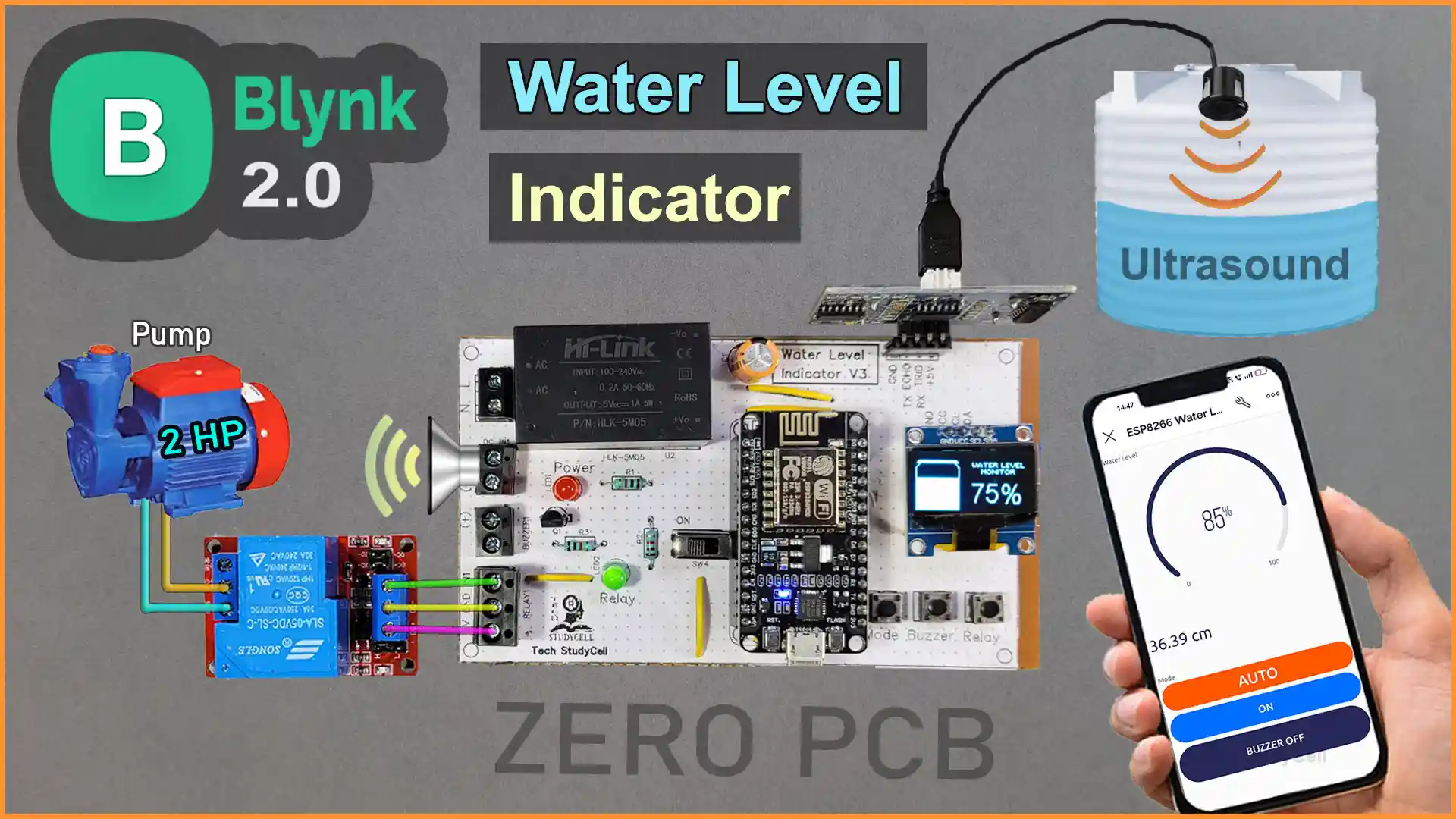
In this ESP8266 IoT project, I have explained how to make a simple IoT-based water level monitoring system using an ultrasonic sensor, ESP8266, and the Blynk IoT platform.


In AUTO mode, it can also control a pump automatically to maintain the water level in the overhead tank.
You can always monitor the water level and MODE on OLED and if the WiFi is connected you can monitor the water level and control the mode and pump from the Blynk IoT app.

For the LOW water level, you will get a Blynk notification and you can also turn on the buzzer alert.
Here I have used a 30A relay, so you can easily control a 1.5HP pump with this water level controller circuit.
So if you follow all the steps, you can easily make this IoT-based water level monitoring system using ESP8266 NodeMCU and Blynk app.
Table of Contents
Required Components for ESP8266 Water Level Sensor

- NodeMCU ESP8266
- SR04M waterproof ultrasonic sensor OR HC-SR04 sensor
- 0.96″ OLED Display
- 1k 0.25watt Resistors – 3 no
- BC547 NPN Transistor
- LED 5mm – 2no
- 2-pin Push Button – 3no
- SPDT slider switch
- 220uF 25V DC Capacitor
- 2-pin Terminal connectors (3 no)
- 3-pin Terminal connectors (1 no)
- 5V DC Buzzer
- AC to DC converter HLK-5M05 5V (Optional)
Circuit of IoT Based Water Level Controller
In the circuit, if you want to use AC voltage, then you have to use an HLK-5M05 AC to DC converter. Otherwise, you can directly give a 5V DC supply to this circuit.
The GPIO D7 & D6 are connected with the Echo & TREG pins of the SR04M-2 waterproof ultrasonic sensor.
The OLED SDA & SCL pins are connected with the D2 & D1 GPIO of NodeMCU.
The control pin of the 30A relay module is connected to the D5, and the D3 pin is connected with the Buzzer.
D12, RX, and D4 pins are connected with pushbuttons for manual control, changing mode, and resetting the buzzer. I have used the INPUT_PULLUP function in Arduino IDE instead of using the pull-up resistors with the pushbuttons.
You can use any other ultrasonic sensor.
PCB Layout for Water Level Monitoring System
Please download the PCB layout, then print it on the A4 page.
Please check the PCB size while printing, it should be the same as mentioned in Layout.
Homemade PCB for the Water Level Indicator

In the tutorial video, I have explained, how you can easily make the complete circuit on zero PCB using the PCB Layout.
Tutorial video on ESP8266 Water Level Controller
During the tutorial video on wireless water level controller, I covered the following topics:
- Quick demo on IoT-based water level monitoring system.
- How to make the water level detector on Zero PCB.
- Set up the Blynk IoT Cloud for ESP8266.
- Steps to add a device in Blynk IoT Cloud.
- Source code for the IoT-based water level sensor.
- Set up the Blynk IoT app to monitor the water level.
Set up Blynk IoT Cloud for the IoT-based Project
You can refer to the following article to set up the new Blynk cloud account
Getting started with New Blynk 2.0 IoT platform
Create Blynk Template
During creating the template, I selected ESP8266 as the hardware and the connection type as WiFi.
Create Datastreams in Blynk Cloud

In the template, I have created the first Datastream (Pin: V1, Datatype: Integer, Min Value: 0, Max Value: 100) to show the water level in the tank in percentage.
Second Datastream (Pin: V2, Datatype: String) will show the distance between the sensor and the water level in cm.
Then created the next 3 Datastreams (Pin: V3 V4 V5, Datatype: Integer, Min Value: 0, Max Value: 1) for changing the Mode, controlling the pump, and resetting the buzzer.
Add Automation in Blynk IoT

I have added Automation to get the LOW water Level notification in the Blynk IoT app.
I have turned on the Condition and Action radio button for the first Datastream V1. Type of Automation will be “Sensor”.
Create Web Dashboard in Blynk Cloud

After that, click and drag 1 Gauge widget, 1 Level widget, and 3 Switch widgets. Then select the related Datastreams for each widget.
Then click on “Save” to save the template.
Add Device in Blynk Cloud using Template
You can refer to the following article to add a device to the Blynk cloud.
PCB for this ESP8266 Water Level Indicator
You can also download the PCB Gerber file and order the PCB from PCBWay.

About PCBWay and their services
You can order any custom design PCBs from PCBWay at very reasonable prices.

PCBWay not only produces FR-4 and Aluminum boards but also advanced PCBs like Rogers, HDI, and Flexible and Rigid-Flex boards, at very affordable prices.
For the online instant quote page please visit – pcbway.com/orderonline
You can also explore different PCB projects from their Open-source community pcbway.com/project/.
For more details please visit the following articles.
Why PCBway
Program ESP8266 NodeMCU with Arduino IDE
For this IoT-based project, I have used the Arduino IDE to program ESP8266 NodeMCU.
First update the Preferences –> Aditional boards Manager URLs: https://raw.githubusercontent.com/espressif/arduino-esp32/gh-pages/package_esp32_dev_index.json, http://arduino.esp8266.com/stable/package_esp8266com_index.json
- Then install the ESP8266 board (3.1.1) from the Board Manager.
- Download the required libraries from the following links:
- Adafruit_SSD1306 Library (Version 2.5.7)
Source Code for Blynk NodeMCU Water Level Sensor
Click on the following buttons to download the source codes for this ESP8266 project.
In the sketch, you have to update only the BLYNK_TEMPLATE_ID, BLYNK_DEVICE_NAME, Auth Token.
/* Fill-in your Template ID (only if using Blynk.Cloud) */
#define BLYNK_TEMPLATE_ID ""
#define BLYNK_DEVICE_NAME ""
#define BLYNK_AUTH_TOKEN ""
Enter the WiFi Credentials.
// Set password to "" for open networks.
char ssid[] = "";
char pass[] = "";
Define Water Level Distance for the empty tank and full tank in CM.
int emptyTankDistance = 150 ;  //Distance when tank is empty
int fullTankDistance =  40 ;  //Distance when tank is full
Define trigger value in percentage, alarm will start when the water level drop below triggerPer.
//Set trigger value in percentage
int triggerPer =   10 ;
Here I have defined the triggerPer 10%, but you can define any value like 5%, 20%, etc.

The ESP8266 will only calculate the water level if the measured distance is between the empty tank distance and the full tank distance.
After doing these changes, please upload the code to ESP8266 NodeMCU.

Install the Water Level Sensor circuit

On the PCB, either you can give AC supply as per the above circuit or you can give 5V DC supply.
***While fitting the ultrasonic sensor in the water tank, please make sure the minimum distance between the sensor and the full tank water level must be greater than 25cm.
I hope you like this IoT-based water level monitoring system using ESP8266 and Blynk IoT app.
Click Here for more such ESP8266 projects.
Please do share your feedback on this IoT project. Thank you for your time.


