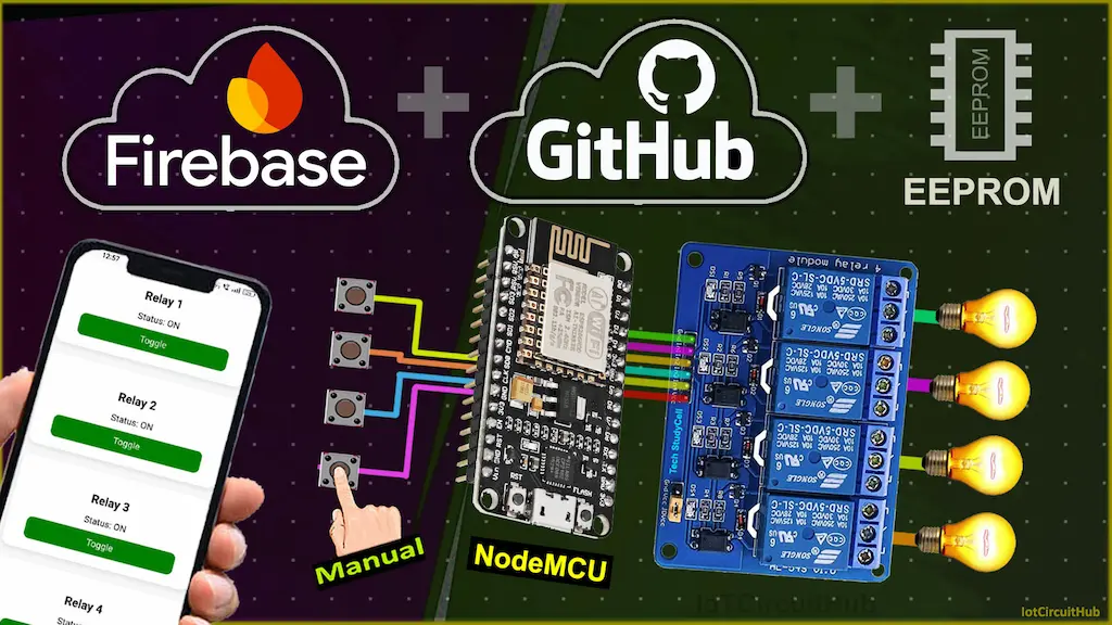
Looking to build a smart home system using the ESP8266 NodeMCU? In this project, you’ll learn how to create a complete IoT Home Automation system using ESP8266 Firebase Realtime Database, and a responsive Web Dashboard—no app required! With support for both manual switch control and remote browser-based control, plus EEPROM memory for state retention, this project offers both reliability and flexibility.

Table of Contents
Project Overview
This ESP8266-based project controls 4 relays, allowing you to switch home appliances ON/OFF manually (using push buttons or latched switches) or remotely via a web dashboard hosted on GitHub. The relay state is synced in real-time with Firebase and is retained after power loss using the EEPROM feature.
Tutorial Video on ESP8266 Firebase Project
Key Features:
- ESP8266 NodeMCU: The heart of the project, connects to Wi-Fi and Firebase.
- Firebase Realtime Database: Stores relay states and updates them instantly from any browser.
- Responsive Web Dashboard: Access and control your relays from any device—PC or mobile.
- Manual Control: Use push buttons or latched switches for local switching.
- EEPROM Memory: Automatically restores the last relay state after reboot or power failure.
- Firebase Authentication: Secures the dashboard with email/password login.
- LED Status Indicator: Onboard LED shows Wi-Fi and Firebase connection status.

How the ESP8266 Firebase Project Works
- ESP8266 connects to Wi-Fi and then initializes Firebase using email/password authentication.
- On boot, the relay states are restored from EEPROM (if enabled).
- The web dashboard, hosted on GitHub, allows you to securely log in and control relays.
- Manual control is handled through push buttons or latched switches using the AceButton library.
- All relay changes are reflected instantly in Firebase, and vice versa – ensuring real-time sync.

Required Components:
Circuit of the ESP8266 NodeMCU project

In the circuit, I have used D1 (GPIO-5), D2 (GPIO-4), D5 (GPIO-14), and D6 (GPIO-12) GPIO pins to control the 4-channel relay module.
And the GPIO SD3 (GPIO-10), D3 (GPIO-0), D7 (GPIO-13), and RX (GPIO-3) are connected with the pushbuttons to control the relay module manually.
If you want to use latched switches for manual control, then refer to the following circuit diagram.

I have used the INPUT_PULLUP function in Arduino IDE instead of using the pull-up resistors with each button.
As per the source code, when the control pins of the relay module receive a LOW signal the relay will turn on, and the relay will turn off for the HIGH signal in the control pin.
I have used a 5V 5Amp mobile charger to supply the circuit.
Please take proper safety precautions while connecting the AC appliances.
Configure the Firebase for the ESP8266
Here are the short steps to configure Firebase for your ESP8266 IoT project:
- Create Firebase Project
- Go to Firebase Console
- Click Add project → Follow prompts
- Enable Realtime Database
- In your project dashboard, go to Build > Realtime Database
- Click Create Database
- Choose Start in test mode (or setup rules later)
- Enable Email/Password Authentication
- Go to Build > Authentication > Sign-in method
- Enable Email/Password
- Create a User
- Go to Users tab in Authentication
- Click Add user → Enter email and password
- Get API Key and Database URL
- Go to Project Settings (gear icon) & Create a Web App.
- Under General > Web API Key → Copy it
- Under Realtime Database → Copy the URL
- Modify the Realtime Database Rules
- go to Build > Realtime Database > Rules tab
- Copy and paste the following details:
{
  "rules": {
    ".read": "auth != null",
    ".write": "auth != null"
  }
}
What these rules mean:
.read: Controls who can read data from the database..write: Controls who can write data to the database.auth != null: Only allow access if the user is authenticated (i.e., logged in).

🎉 PCBWay is celebrating its 11th Anniversary — and you’re invited! Join the celebration from June 18 to July 18, 2025, and unlock rewards, coupons, and a chance to win exciting prizes.

🔓 Event Rules: Complete any of 6 simple tasks — like reading their letter, watching a video, placing an order, or uploading a project — to unlock cards. Collect all 6 cards to earn an extra lucky draw chance!
Be part of PCBWay’s journey of innovation and sustainability. Explore Now
Program ESP8266 NodeMCU with Arduino IDE
In the tutorial video, I explained all the steps for programming the NodeMCU using Arduino IDE.
- Update the Preferences –> Aditional boards Manager URLs: https://dl.espressif.com/dl/package_esp32_index.json, http://arduino.esp8266.com/stable/package_esp8266com_index.json
- Then install the ESP8266 board (version: 3.1.2) from the Board Manager, or Click Here to download the ESP8266 board.
- You need the following libraries:
- Firebase_ESP_Client by Mobizt (version 4.4.17)
- ArduinoJson (version 7.4.1)
- AceButton (version 1.10.1)
Source Code for the ESP8266 Firebase Relay Project
To make your ESP8266 project work with Wi-Fi and Firebase, you must update the placeholders in your code with your actual credentials.
Here’s what each field means and how to fill it:
Update These Fields in the Code:
// Wi-Fi credentials
const char* ssid = "YourWiFiName";          // 🔹 Your Wi-Fi name (SSID)
const char* password = "YourWiFiPassword";  // 🔹 Your Wi-Fi password

// Firebase credentials
#define API_KEY "YourFirebaseWebAPIKey"          // 🔹 Found in Project Settings > General
#define DATABASE_URL "https://your-project-id.firebasedatabase.app/"  // 🔹 From Realtime Database URL
#define USER_EMAIL "[email protected]"  // 🔹 Firebase Authentication email
#define USER_PASSWORD "your-auth-password"        // 🔹 Firebase Authentication password
📌 Where to find them:
- API_KEY:
- Go to Firebase Console > Your Project > ⚙️ Settings > General.
- Scroll down to “Web API Key”.
- DATABASE_URL:
- Go to Realtime Database in Firebase.
- The URL will look like:
https://your-project-id-default-rtdb.firebasedatabase.app/
- USER_EMAIL / USER_PASSWORD:
- Go to the Authentication tab > Add a new user with email & password.
// ==== Feature Flags ====
bool useEEPROM = true;       // Enable EEPROM memory restore (true = Active)
bool useLatchedSwitch = true; // true = latched switch, false = push button
Also, Enable/Disable the EEPROM with useEEPROM flag.
If you use latched switches for manual control, then make the flag useLatchedSwitch true, and for the push button, make it false.
Detailed line-by-line explanation of the source code:
Library Includes and Namespace
#include <ESP8266WiFi.h>
#include <Firebase_ESP_Client.h>
#include <AceButton.h>
#include <EEPROM.h>
using namespace ace_button;Explanation:
ESP8266WiFi.h: Required for Wi-Fi connectivity on ESP8266 boards.Firebase_ESP_Client.h: Main library for accessing Firebase Realtime Database.AceButton.h: Handles debouncing and event-based input for push buttons or latched switches.EEPROM.h: Used for reading/writing persistent data to EEPROM memory on the ESP8266.using namespace ace_button;: Allows direct use ofAceButtonwithout needing to prefix it withace_button::.
Wi-Fi and Firebase Credentials
const char* ssid = "";
const char* password = "";

#define API_KEY ""
#define DATABASE_URL ""
#define USER_EMAIL ""
#define USER_PASSWORD ""Explanation:
ssidandpassword: Your Wi-Fi network name and password.API_KEY: Firebase Web API key from your project settings.DATABASE_URL: Firebase Realtime Database root URL.USER_EMAILandUSER_PASSWORD: Firebase Authentication credentials (email/password login method).
Feature Flags and Firebase State
bool useEEPROM = true;
bool useLatchedSwitch = true;

bool firebaseInitialized = false;
bool firebaseWasReady = false;Explanation:
useEEPROM: Enables saving and restoring relay states from EEPROM memory.useLatchedSwitch: Determines if manual switches are toggling (latched) or momentary (push button).firebaseInitialized: Tracks if Firebase has been successfully initialized.firebaseWasReady: Flags when Firebase becomes ready for the first time.
GPIO Pin Definitions
#define RELAY1 5
#define RELAY2 4
#define RELAY3 14
#define RELAY4 12

#define SwitchPin1 10
#define SwitchPin2 0
#define SwitchPin3 13
#define SwitchPin4 3

#define wifiLed 16Explanation:
RELAY1–4: GPIO pins connected to the relays (Active LOW).SwitchPin1–4: GPIO pins for manual switches.wifiLed: Optional onboard LED to indicate Wi-Fi status.
Firebase and Button Setup
FirebaseData fbdo;
FirebaseAuth auth;
FirebaseConfig config;

ButtonConfig config1;
ButtonConfig config2;
ButtonConfig config3;
ButtonConfig config4;

AceButton button1(&config1, SwitchPin1);
AceButton button2(&config2, SwitchPin2);
AceButton button3(&config3, SwitchPin3);
AceButton button4(&config4, SwitchPin4);Explanation:
fbdo: The Firebase data object used for communication.auth: Contains Firebase email/password auth credentials.config: Stores Firebase API key and DB URL.config1–4: AceButton configs for each button input.button1–4: Create AceButton objects linked to their respective pins and configs.
EEPROM Addresses and Helper Functions
#define EEPROM_SIZE 10
#define RELAY1_ADDR 0
#define RELAY2_ADDR 1
#define RELAY3_ADDR 2
#define RELAY4_ADDR 3Explanation:
Defines the EEPROM size and allocates addresses for storing each relay’s on/off state.
EEPROM Read/Write Functions
void writeRelayStateToEEPROM(uint8_t addr, bool state) {
  if (useEEPROM) {
    EEPROM.write(addr, state ? 1 : 0);
    EEPROM.commit();
  }
}

bool readRelayStateFromEEPROM(uint8_t addr) {
  return EEPROM.read(addr) == 1;
}Explanation:
writeRelayStateToEEPROM(): Saves relay state to EEPROM (1 for ON, 0 for OFF).readRelayStateFromEEPROM(): Reads the saved relay state and returns it as a boolean.
Relay Control Function
void setRelay(int relayPin, int eepromAddr, bool state) {
  digitalWrite(relayPin, state ? LOW : HIGH);  // Active LOW
  writeRelayStateToEEPROM(eepromAddr, state);
}Explanation:
- Activates/deactivates the relay (
LOW= ON,HIGH= OFF) and stores the state in EEPROM.
Button Event Handler
void handleEvent(AceButton* button, uint8_t eventType, uint8_t) {
  int pin = button->getPin();
  bool newState = false;

  if (useLatchedSwitch) {
    newState = (eventType == AceButton::kEventPressed);
  } else {
    if (eventType != AceButton::kEventReleased) return;
    switch (pin) {
      case SwitchPin1: newState = !(digitalRead(RELAY1) == LOW); break;
      case SwitchPin2: newState = !(digitalRead(RELAY2) == LOW); break;
      case SwitchPin3: newState = !(digitalRead(RELAY3) == LOW); break;
      case SwitchPin4: newState = !(digitalRead(RELAY4) == LOW); break;
    }
  }

  switch (pin) {
    case SwitchPin1:
      setRelay(RELAY1, RELAY1_ADDR, newState);
      if (Firebase.ready()) Firebase.RTDB.setBool(&fbdo, "/relay1", newState);
      Serial.println("Relay1 toggled manually");
      break;
    case SwitchPin2:
      setRelay(RELAY2, RELAY2_ADDR, newState);
      if (Firebase.ready()) Firebase.RTDB.setBool(&fbdo, "/relay2", newState);
      Serial.println("Relay2 toggled manually");
      break;
    case SwitchPin3:
      setRelay(RELAY3, RELAY3_ADDR, newState);
      if (Firebase.ready()) Firebase.RTDB.setBool(&fbdo, "/relay3", newState);
      Serial.println("Relay3 toggled manually");
      break;
    case SwitchPin4:
      setRelay(RELAY4, RELAY4_ADDR, newState);
      if (Firebase.ready()) Firebase.RTDB.setBool(&fbdo, "/relay4", newState);
      Serial.println("Relay4 toggled manually");
      break;
  }
}Explanation:
- Determines which button was pressed and how to handle it.
- Supports two modes: latched switch (toggle on press) and push button (toggle on release).
- Based on pin pressed, it updates the relay state, writes to EEPROM, and syncs to Firebase.
setup() Function
void setup() {
  Serial.begin(115200);

if (useEEPROM) EEPROM.begin(EEPROM_SIZE);Explanation:
Serial.begin(115200): Starts the serial monitor for debugging at a baud rate of 115200.EEPROM.begin(EEPROM_SIZE): Initializes EEPROM memory if EEPROM usage is enabled.
  pinMode(RELAY1, OUTPUT);
  pinMode(RELAY2, OUTPUT);
  pinMode(RELAY3, OUTPUT);
pinMode(RELAY4, OUTPUT);Explanation:
This block sets each relay pin as an output. These relays are controlled by setting the pins LOW (to activate) or HIGH (to deactivate), as they are Active LOW relays.
  if (useEEPROM) {
    setRelay(RELAY1, RELAY1_ADDR, readRelayStateFromEEPROM(RELAY1_ADDR));
    setRelay(RELAY2, RELAY2_ADDR, readRelayStateFromEEPROM(RELAY2_ADDR));
    setRelay(RELAY3, RELAY3_ADDR, readRelayStateFromEEPROM(RELAY3_ADDR));
    setRelay(RELAY4, RELAY4_ADDR, readRelayStateFromEEPROM(RELAY4_ADDR));
  } else {
    digitalWrite(RELAY1, HIGH);
    digitalWrite(RELAY2, HIGH);
    digitalWrite(RELAY3, HIGH);
    digitalWrite(RELAY4, HIGH);
}Explanation:
- If
useEEPROMis enabled, each relay state is restored from EEPROM to resume the last known state after power loss. - If EEPROM is not used, all relays are turned OFF by default (set to HIGH).
  pinMode(SwitchPin1, INPUT_PULLUP);
  pinMode(SwitchPin2, INPUT_PULLUP);
  pinMode(SwitchPin3, INPUT_PULLUP);
  pinMode(SwitchPin4, INPUT_PULLUP);

  pinMode(wifiLed, OUTPUT);
digitalWrite(wifiLed, HIGH);Explanation:
- All switches are configured as
INPUT_PULLUP, meaning they’re HIGH by default and go LOW when pressed or latched to GND. - The Wi-Fi LED is set to ON (HIGH) initially, indicating no Wi-Fi connection yet.
  waitForWiFi();
digitalWrite(wifiLed, LOW);Explanation:
waitForWiFi()is a custom function that keeps trying to connect to the configured Wi-Fi network.- If successful, the Wi-Fi LED is turned OFF (LOW).
- If Wi-Fi connection fails after 10 seconds, the ESP restarts.
  button1.getButtonConfig()->setEventHandler(handleEvent);
  button2.getButtonConfig()->setEventHandler(handleEvent);
  button3.getButtonConfig()->setEventHandler(handleEvent);
button4.getButtonConfig()->setEventHandler(handleEvent);Explanation:
Each button is assigned the handleEvent function, which processes press/release events and toggles the relay accordingly.
  Serial.println("Initializing Firebase...");

  config.api_key = API_KEY;
  auth.user.email = USER_EMAIL;
  auth.user.password = USER_PASSWORD;
  config.database_url = DATABASE_URL;

  Firebase.begin(&config, &auth);
Firebase.reconnectWiFi(true);Explanation:
- Configures Firebase credentials and initializes the Firebase connection.
Firebase.reconnectWiFi(true): Ensures Firebase will automatically reconnect if Wi-Fi drops.
  unsigned long timeout = millis() + 10000;
  while (!Firebase.ready()) {
    if (millis() > timeout) {
      Serial.println("Firebase failed to connect in 10s. Restarting ESP...");
      delay(1000);
      ESP.restart();
    }
    delay(200);
    Serial.print(".");
  }

  Serial.println("\nFirebase connected successfully.");
  firebaseInitialized = true;
}Explanation:
- Waits for Firebase to become ready.
- If not ready in 10 seconds, prints an error and restarts the ESP8266.
- Once ready, prints confirmation and sets
firebaseInitializedto true.
loop() Function:
void loop() {
  bool wifiConnected = WiFi.status() == WL_CONNECTED;
digitalWrite(wifiLed, wifiConnected ? LOW : HIGH);Explanation:
- Checks if the ESP8266 is connected to Wi-Fi.
- Turns the Wi-Fi LED OFF if connected, ON if disconnected.
  bool firebaseNowReady = Firebase.ready();

  if (firebaseNowReady && !firebaseWasReady) {
    Serial.println("Firebase first-time ready. Pushing EEPROM state → Firebase");
    firebaseWasReady = true;

    if (useEEPROM) {
      Firebase.RTDB.setBool(&fbdo, "/relay1", readRelayStateFromEEPROM(RELAY1_ADDR));
      Firebase.RTDB.setBool(&fbdo, "/relay2", readRelayStateFromEEPROM(RELAY2_ADDR));
      Firebase.RTDB.setBool(&fbdo, "/relay3", readRelayStateFromEEPROM(RELAY3_ADDR));
      Firebase.RTDB.setBool(&fbdo, "/relay4", readRelayStateFromEEPROM(RELAY4_ADDR));
    }

    return;
}Explanation:
- Detects the first time Firebase becomes ready.
- Syncs current EEPROM relay states to the Firebase database so the web dashboard shows the correct values.
  if (firebaseNowReady) {
    if (Firebase.RTDB.getBool(&fbdo, "/relay1")) {
      setRelay(RELAY1, RELAY1_ADDR, fbdo.boolData());
    }
    if (Firebase.RTDB.getBool(&fbdo, "/relay2")) {
      setRelay(RELAY2, RELAY2_ADDR, fbdo.boolData());
    }
    if (Firebase.RTDB.getBool(&fbdo, "/relay3")) {
      setRelay(RELAY3, RELAY3_ADDR, fbdo.boolData());
    }
    if (Firebase.RTDB.getBool(&fbdo, "/relay4")) {
      setRelay(RELAY4, RELAY4_ADDR, fbdo.boolData());
    }
}Explanation:
- Reads each relay’s state from Firebase and updates the corresponding relay output and EEPROM.
- Keeps the hardware state in sync with the database in real-time.
  button1.check();
  button2.check();
  button3.check();
  button4.check();

  delay(10);
}Explanation:
- Continuously checks each button for events like press or release.
delay(10)is a short pause to avoid CPU overload and help with button debouncing.
Deploy Web Dashboard on GitHub Pages
- Create a GitHub account (if not already).
- Create a new repository, e.g.,
esp8266-dashboard. - Upload your HTML (index.html) to the repo.
- Go to Settings → Pages.
- Under Source, choose
mainbranch and/ (root)folder. - Click Save – GitHub will generate a public URL like:
https://your-username.github.io/esp8266-dashboard/ - Open the URL to view your live dashboard!
Test the ESP8266 Firebase Project
Once the project is uploaded:
- Open the Serial Monitor to confirm Wi-Fi and Firebase connections.
- Control relays via:
- Your web dashboard
- The physical push buttons
All changes are reflected in real-time on Firebase!
This process ensures that your ESP8266 home automation setup is fully functional and can be controlled both physically and remotely via the Web Dashboard through the internet.
I hope you like this Smart house IoT project idea with the Firebase NodeMCU ESP8266.
Click Here for more such ESP8266 projects.
Please do share your feedback on this IoT project. Thank you for your time.


