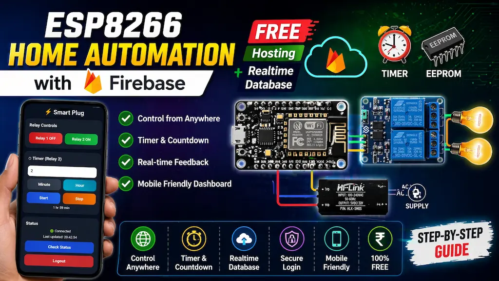
Want to build your own IoT Home Automation System using ESP8266 NodeMCU? In this ESP8266 Firebase project, we use Firebase Realtime Database, Firebase Hosting, and a mobile-friendly web dashboard to control home appliances from anywhere in the world.

This is one of the best low-cost ESP8266 Firebase projects because it offers cloud control, timer automation, live feedback, and manual switch operation — all using the free Firebase plan.
Table of Contents
Tutorial Video on ESP8266 Firebase Project
Key Features of ESP8266 Firebase Project
- ✅ Control 2 relays from anywhere using internet through a free hosted Firebase web dashboard, with real-time ON/OFF feedback and mobile-friendly access from Android, iPhone, tablet, or PC.
- ✅ Built using ESP8266 NodeMCU + Firebase Realtime Database, providing fast cloud communication for remote appliance control from anywhere in the world.
- ✅ Includes a timer function for Relay 2 with minute/hour selection, live countdown display, and automatic relay OFF after timer completion.
- ✅ Supports manual switch control with both latched switch and push button mode, selectable directly in the code.
- ✅ Compatible with both Active LOW and Active HIGH relay modules, making it suitable for different relay boards.
- ✅ Features EEPROM memory backup to save relay states and timer data, allowing timer resume after power failure.
- ✅ Includes auto WiFi reconnect, secure Firebase email/password login, dashboard device status check button, and last updated time display.
- ✅ Optimized for low Firebase resource usage, making it ideal for free plan users.
Firebase Services Used
This project uses:
- Firebase Realtime Database: Used for real-time communication between dashboard and ESP8266.
- Firebase Hosting: Used to host the mobile dashboard online for free.
- Firebase Authentication: Used for secure email/password login.

How This ESP8266 Firebase Project Works
- ESP8266 Connects to WiFi: After powering ON, the ESP8266 connects to your WiFi router.
- Login to Firebase: ESP8266 securely logs in using Firebase Authentication.
- Reads Cloud Commands: It continuously checks Firebase Realtime Database for:
- Relay ON/OFF commands
- Timer start/stop
- Remaining countdown time
- Controls Relays: When a button is pressed on the dashboard:
- Firebase receives command
- ESP8266 reads instantly
- Relay switches ON/OFF
- Sends Real-Time Feedback: The relay status is updated back to Firebase so dashboard always shows current state.
Required Components for ESP8266 Project
- ESP8266 NodeMCU WiFi module
- 2-channel relay module (active-LOW)
- 5-mm LED + 220Ω resistor for WiFi status
- 2 latched switches (ON/OFF toggle or rocker switch)
- 5A 3 pin socket
- Jumper wires
Circuit of the Smart Plug using NodeMCU

Pin Configuration
| Function | NodeMCU Pin | GPIO |
|---|---|---|
| Relay 1 | D5 | GPIO14 |
| Relay 2 | D6 | GPIO12 |
| Switch 1 | D1 | GPIO5 |
| Switch 2 | D2 | GPIO4 |
| WiFi LED | D0 | GPIO16 |
The AC sockets are connected across the NO and COM terminals of the relays.
You can use any 5V 1Amp mobile charger to supply the circuit.
Please take proper safety precautions while working with High Voltage.
Configure the Firebase for the ESP8266
Here are the short steps to configure Firebase for your ESP8266 IoT project:
- Create Firebase Project
- Go to Firebase Console
- Click Add project → Follow prompts
- Enable Realtime Database
- In your project dashboard, go to Database & Storage > Realtime Database
- Click Create Database
- Choose Start in test mode (we will setup rules later)
- Enable Email/Password Authentication
- Go to Security > Authentication > Sign-in method
- Enable Email/Password
- Create a User
- Go to Users tab in Authentication
- Click Add user → Enter email and password
- Get API Key and Database URL
- Go to Project Settings (gear icon) & Create a Web App.
- Under General > Web API Key → Copy it
- Under Realtime Database → Copy the URL
Modify the Realtime Database Rules
{
  "rules": {
    ".read": "auth != null",
    ".write": "auth != null"
  }
}
What these rules mean:
.read: Controls who can read data from the database..write: Controls who can write data to the database.auth != null: Only allow access if the user is authenticated (i.e., logged in).
Real-Time Database Structure for ESP8266 Firebase Project
Use this JSON in Firebase:
{
  "relay1": false,
  "relay2": false,
  "timerActive": false,
  "remaining": 0,
  "statusRequest": false,
  "statusReply": false,
  "deviceStatus": "Disconnected"
}

Why Choose PCBWay?
Factory-Direct PCBs with Competitive Advantages
- High-quality PCBs at competitive factory-direct prices
- Fast PCB production with lead times starting from 24 hours*
- Experienced team of 90+ engineers and technical specialists
- 99% on-time delivery with reliable global shipping partners
- Trusted by customers worldwide for quality and consistency
- Years of proven manufacturing expertise
- 24/7 production and customer support
- Low minimum order quantities, ideal for prototypes and small batches

Their experienced engineering team delivers high-quality designs for everything from simple boards to complex multi-layer and rigid-flex PCBs.
For more details: PCBWay – PCB manufacturing and PCB Assembly
Program ESP8266 NodeMCU with Arduino IDE
In the tutorial video, I explained all the steps for programming the NodeMCU using Arduino IDE.
- Update the Preferences –> Aditional boards Manager URLs: https://dl.espressif.com/dl/package_esp32_index.json, http://arduino.esp8266.com/stable/package_esp8266com_index.json
- Then install the ESP8266 board (version: 3.1.2) from the Board Manager, or Click Here to download the ESP8266 board.
- You need the following libraries:
- Firebase_ESP_Client (version 4.4.17)
- ArduinoJson (version 7.4.1)
Source Code for the ESP8266 Firebase Relay Project
To make your ESP8266 project work with Wi-Fi and Firebase, you must update the placeholders in your code with your actual credentials.
Here’s what each field means and how to fill it:
Update These Fields in the Code:
// Wi-Fi credentials
#define WIFI_SSID "YourWiFiName";          // 🔹 Your Wi-Fi name (SSID)
#define WIFI_PASSWORD "YourWiFiPassword";  // 🔹 Your Wi-Fi password

// Firebase credentials
#define API_KEY "YourFirebaseWebAPIKey"          // 🔹 Found in Project Settings > General
#define DATABASE_URL "https://your-project-id.firebasedatabase.app/"  // 🔹 From Realtime Database URL
#define USER_EMAIL "[email protected]"  // 🔹 Firebase Authentication email
#define USER_PASSWORD "your-auth-password"        // 🔹 Firebase Authentication password
📌 Where to find them:
- API_KEY:
- Go to Firebase Console > Your Project > ⚙️ Settings > General.
- Scroll down to “Web API Key”.
- DATABASE_URL:
- Go to Realtime Database in Firebase.
- The URL will look like:
https://your-project-id-default-rtdb.firebasedatabase.app/
- USER_EMAIL / USER_PASSWORD:
- Go to the Authentication tab > to get the email & password.
Update the Flags
// ---------- FLAGS ----------
#define USE_EEPROM            1   //1=enable
#define USE_LATCHED_SWITCH    1   //1=latched ,0=push button
#define RELAY_ACTIVE_LOW      1   //1=active low ,0=active high relay
Also, Enable/Disable the EEPROM with USE_EEPROM flag.
If you use latched switches for manual control, then make the flag USE_LATCHED_SWITCH 1, and for the push button, make it 0.
Next, for the Active-LOW relay module, set the RELAY_ACTIVE_LOW flag to 1; for the Active-HIGH relay module, set it to 0.
Detailed line-by-line explanation of the source code:
Below is a detailed explanation of your ESP8266 Firebase Home Automation project code. Each code block is followed by a clear paragraph explaining how it works and why it is used.
Required Libraries
#include <ESP8266WiFi.h>
#include <Firebase_ESP_Client.h>
#include <EEPROM.h>
These three libraries are the foundation of the project. ESP8266WiFi.h allows the NodeMCU to connect with a WiFi network so it can access the internet. Firebase_ESP_Client.h is used for secure communication with Firebase Realtime Database, letting the ESP8266 send and receive data from the cloud. EEPROM.h provides internal non-volatile memory storage, which means relay states and timer values can be saved even after power loss.
WiFi and Firebase Credentials
#define WIFI_SSID       ""
#define WIFI_PASSWORD   ""

#define API_KEY         ""
#define DATABASE_URL    ""
#define USER_EMAIL      ""
#define USER_PASSWORD   ""
These definitions store your network and Firebase login details. The ESP8266 uses the WiFi SSID and password to connect to your router. Firebase API key, database URL, and authentication email/password allow secure login to your Firebase project. Once entered correctly, the board can communicate with your online dashboard from anywhere.
Feature Flags
#define USE_EEPROM            1
#define USE_LATCHED_SWITCH    1
#define RELAY_ACTIVE_LOW      1
These flags make the code flexible and reusable. USE_EEPROM enables or disables memory saving. If enabled, relay and timer states are stored after changes. USE_LATCHED_SWITCH selects whether you are using normal wall switches or push buttons. RELAY_ACTIVE_LOW selects the relay logic type. Many relay boards turn ON when pin goes LOW, so this flag lets the same code support both active LOW and active HIGH modules.
Timing Settings
#define FIREBASE_READ_INTERVAL      1000
#define REMAINING_UPDATE_INTERVAL   10000
#define TIMER_SAVE_INTERVAL         10000
#define WIFI_RECONNECT_INTERVAL     10000
#define SWITCH_DEBOUNCE_TIME        50
#define RELAY_BOOT_DELAY            500
These values control how often background tasks run. Firebase is checked every 1 second for new commands. Remaining timer data is updated every 10 seconds to reduce Firebase writes. EEPROM timer data is also saved every 10 seconds to protect memory life. WiFi reconnect attempts happen every 10 seconds if disconnected. Switch debounce of 50 ms prevents false triggers from noisy mechanical switches. Boot delay of 500 ms prevents relay flicker during startup.
Pin Definitions
#define RELAY1 D5
#define RELAY2 D6
#define SW1    D1
#define SW2    D2
#define LEDPIN D0
These lines assign hardware pins. Relay outputs are connected to D5 and D6. Manual switches are connected to D1 and D2. The LED pin is used as a timer indicator. When the timer is running, the LED changes state so the user gets a visual status signal.
EEPROM Memory Addresses
#define ADDR_R1            0
#define ADDR_R2            1
#define ADDR_TIMER         10
#define EEPROM_MAGIC_ADDR  100
#define EEPROM_MAGIC_VAL   55
EEPROM is like tiny permanent memory inside the ESP8266. Specific addresses are reserved to store relay states and timer values. The magic value is used to verify whether valid data already exists. If not found, the system assumes first boot and starts with relays OFF.
Firebase Objects
FirebaseData fbdo;
FirebaseAuth auth;
FirebaseConfig config;
These objects are required by the Firebase library. FirebaseData handles communication requests. FirebaseAuth stores login credentials. FirebaseConfig stores API key and database URL. Together they create the connection between ESP8266 and Firebase.
Relay State Variables
bool relay1State = false;
bool relay2State = false;
These variables track whether each relay is ON or OFF. Instead of repeatedly reading hardware pins, the code stores the current state in memory. This makes logic faster and easier to manage.
Timer Variables
bool timerRunning = false;
unsigned long timerStart = 0;
unsigned long timerDuration = 0;
These variables control the timer system. timerRunning tells whether the countdown is active. timerStart stores the starting time using millis(). timerDuration stores total countdown time in milliseconds.
Relay Control Function
void setRelay(uint8_t pin, bool state)
This function turns relays ON or OFF. It automatically checks whether the relay board is active LOW or active HIGH. Because of this, the rest of the code only uses logical ON/OFF states and does not need to worry about electrical polarity.
Save Relay States to EEPROM
void saveRelayState()
Whenever a relay changes, this function stores the new state in EEPROM. It first checks whether the stored value already matches the new one. If unchanged, it avoids rewriting memory. This helps extend EEPROM life because memory has limited write cycles.
Load Relay States
void loadRelayState()
During startup, this function checks for the magic value. If valid data exists, saved relay states are restored. Otherwise, both relays are set OFF. This gives reliable startup behavior even after power failure.
WiFi Connection
void connectWiFi()
This function starts WiFi station mode and attempts connection using your router credentials. Progress dots are printed on Serial Monitor. If connection fails after 15 seconds, the function exits. If successful, the local IP address is displayed.
Automatic WiFi Reconnect
void maintainWiFi()
This function runs continuously in the main loop. If WiFi is disconnected, it retries every 10 seconds. This makes the system much more stable than rebooting the board whenever WiFi drops.
Firebase Connection
void connectFirebase()
This function loads API key, database URL, email, and password into Firebase configuration. Then it starts the Firebase connection and enables automatic WiFi reconnection support.
Setup Function
void setup()
This is the startup routine. Serial Monitor begins first for debugging. EEPROM starts if enabled. Relay pins are configured as outputs and initially forced OFF to prevent accidental switching. Switch pins are configured with internal pull-up resistors. Saved states are loaded, then restored after a short delay. WiFi and Firebase are connected. Finally, saved timer data is checked and resumed if necessary.
Manual Switch Handling
void checkSwitches()
This function reads physical switches. If latched mode is selected, relay state directly follows switch position. If push-button mode is selected, each press toggles the relay. Debounce timing prevents accidental multiple triggers. Whenever a relay changes, Firebase and EEPROM are updated immediately.
Reading Firebase Commands
void readFirebase()
This is the cloud control engine. It checks Firebase for relay commands, timer commands, and status requests. If dashboard buttons were pressed online, the ESP8266 receives those values here and updates hardware outputs accordingly.
Timer Start Logic
if(cmd && !timerRunning)
When timerActive becomes true from the dashboard, the ESP8266 reads the remaining seconds value. It converts seconds to milliseconds, starts the timer, turns Relay 2 ON, updates Firebase feedback, and activates the LED indicator.
Timer Stop Logic
if(!cmd && timerRunning)
If the dashboard sends stop command, the timer ends immediately. LED turns OFF and saved timer data is cleared.
Status Request System
if(Firebase.RTDB.getBool(&fbdo,"/statusRequest"))
This is your smart low-resource online detection method. When dashboard presses “Check Status,” Firebase writes statusRequest=true. ESP8266 reads it and replies by writing statusReply=true, then resets the request flag. If dashboard receives the reply, it shows Connected.
Timer Handling Function
void handleTimer()
This function continuously calculates elapsed time while timer is active. If time finishes, Relay 2 turns OFF automatically, Firebase values are reset, LED turns OFF, and EEPROM is cleared.
Remaining Time Updates
if(millis()-lastRemainingPush > REMAINING_UPDATE_INTERVAL)
Instead of updating Firebase every second, the code updates remaining time every 10 seconds. This greatly reduces Firebase usage while still keeping dashboard data accurate.
EEPROM Timer Save
if(millis()-lastTimerSave > TIMER_SAVE_INTERVAL)
Every 10 seconds, the remaining timer value is saved into EEPROM. If power fails, countdown can resume from nearly the same point after restart.
Main Loop
void loop()
This function runs forever. It keeps WiFi alive, checks switches, reads Firebase commands every second, and processes the timer continuously. All automation behavior happens here.
This project combines local hardware control with cloud IoT features. Physical switches, mobile dashboard, relay control, timer automation, EEPROM backup, Firebase hosting, and real-time remote access are all integrated into one professional ESP8266 smart home system.
Deploy Web Dashboard on Firebase Hosting
Please refer to the following article for a step-by-step guide to deploy the web-dashboard HTML on Firebase Hosting for FREE.
Steps to deploy HTML files on Firebase hosting
Test the ESP8266 Firebase Project

Once the project is uploaded:
- Open the Serial Monitor to confirm Wi-Fi and Firebase connections.
- Control relays via:
- Your web dashboard
- The physical push buttons
All changes are reflected in real-time on Firebase
Conclusion
This ESP8266 Home Automation with Firebase Hosting + Realtime Database project is a powerful and professional IoT solution using free cloud tools. It combines relay control, timer automation, manual switch support, EEPROM backup, and mobile dashboard access into one complete smart home project.
If you want to learn ESP8266 IoT projects, this is one of the best practical builds to start with.
Click Here for more such ESP8266 projects.


