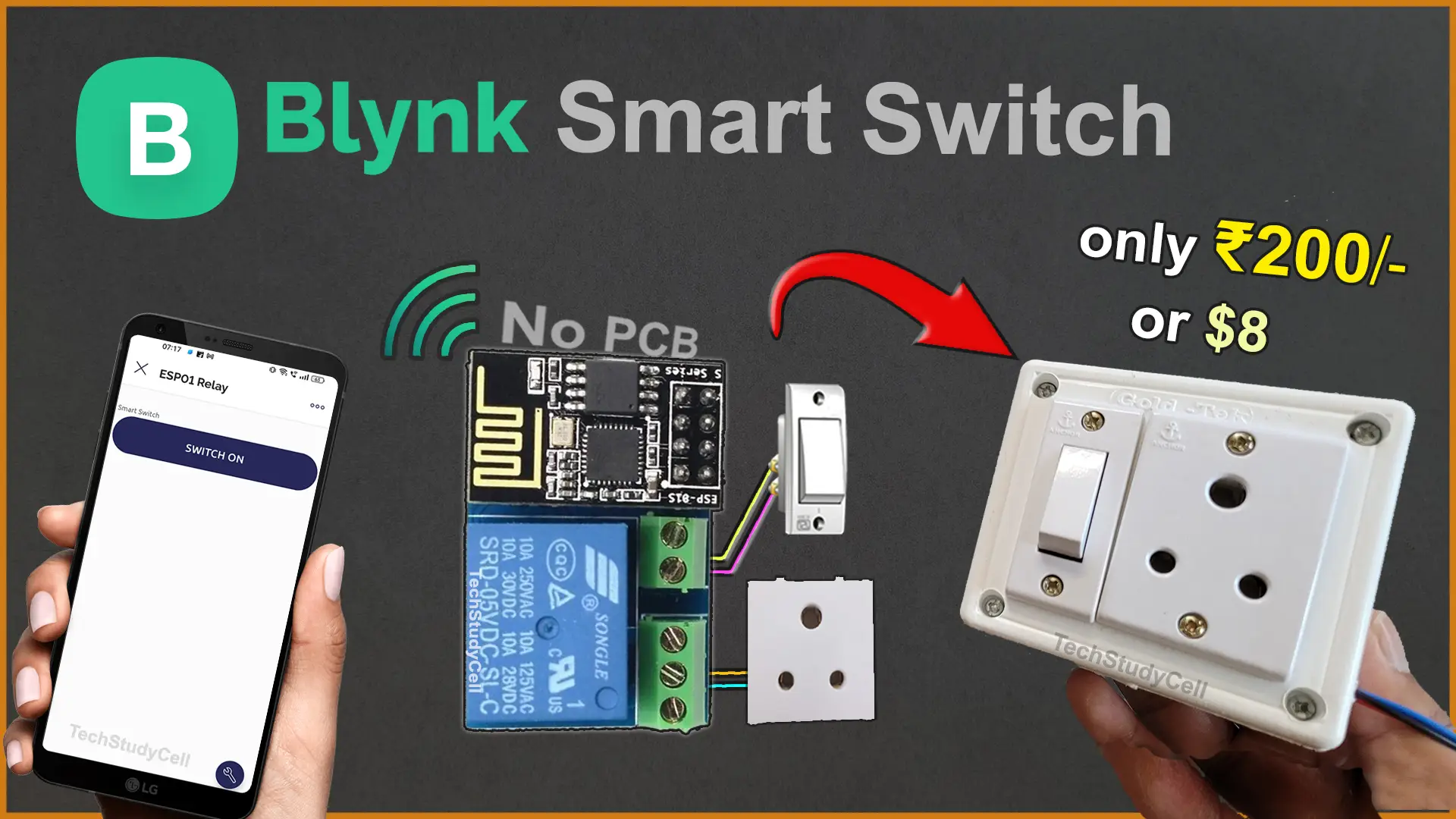
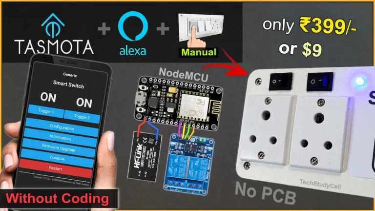
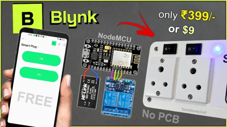
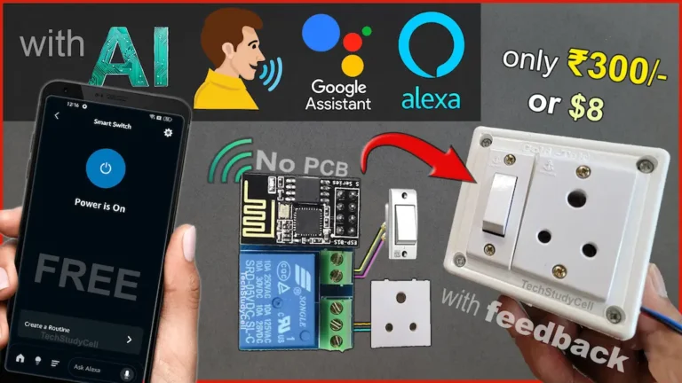
In this ESP8266 project, I have explained how to make an ESP01 relay Project using the Blynk IoT application and manual switch. To make this IoT-based home automation project, you need “ESP-01/01s relay v4.0” and ESP01.
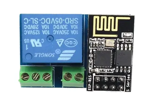
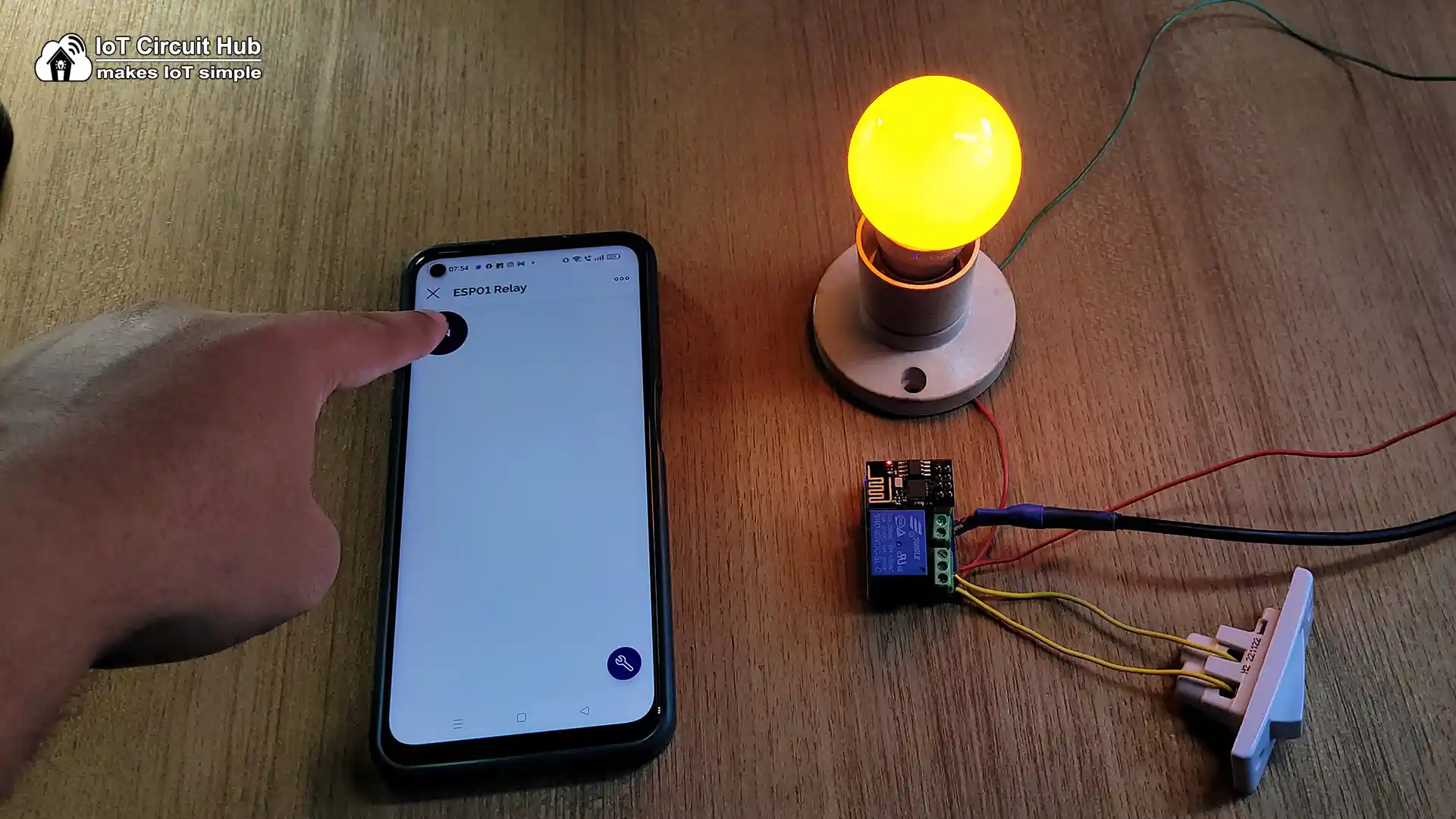
I have used the FREE plan of Blynk for this ESP01 home automation project. You can buy the “ESP-01/01s relay v4.0” from any online store.
So if you follow all the steps, you can easily make this IoT project with ESP-01 ESP8266 and Blynk app.
Table of Contents
Required Components:
Circuit of the ESP01 Relay IoT project
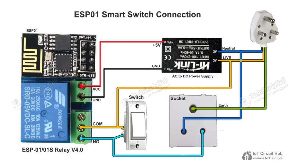
In the circuit, you can use any 5V DC power supply.
The switch is connected across the NO and COM contact of the relay. As the switch is not connected to the ESP01, so you can’t monitor the real-time feedback.
The relay control pin is connected to the GPIO-0 of the ESP-01.
Instead of the socket, you can also connect a lamp with the relay as per the following circuit.
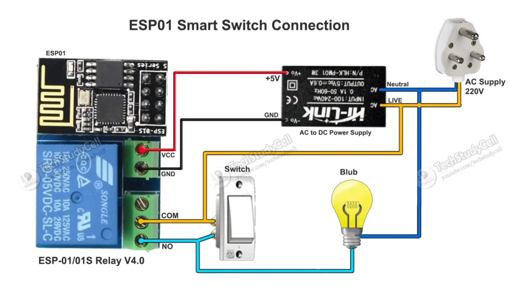
Please take proper safety precautions while connecting the AC appliances.
Tutorial video on ESP-01 Relay with Blynk IoT
In this IoT tutorial video, I have covered the following topics:
- Explained Circuit and Source code for the Blynk ESP-01 control relay.
- Configure the Blynk cloud account for ESP8266.
- Configure the Blynk IoT app for the ESP8266 project.
- How to add automation in the Blynk IoT app.
Set up Blynk Cloud for the ESP01 IoT Project
You can refer to the following article to set up the new Blynk cloud account
Getting started with New Blynk 2.0 IoT platform
Create Blynk Template
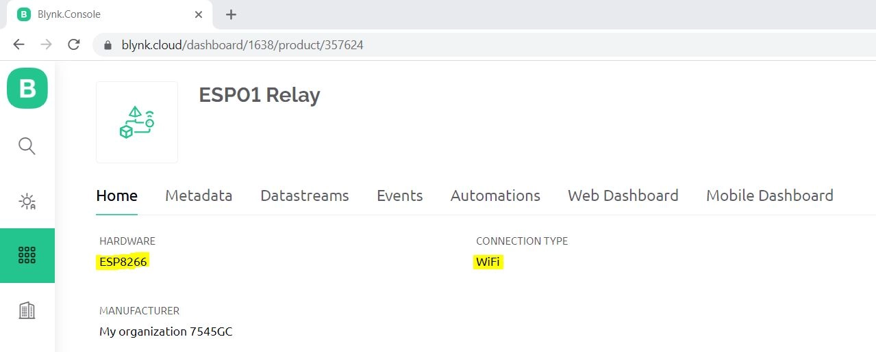
During creating the template, I selected ESP8266 as the hardware and the connection type as WiFi.
Create Datastreams in Blynk Cloud

In the template, I have created the 1 Datastream (Pin: V1, Datatype: Integer, Min Value: 0, Max Value: 1) to control the relay.
Add Automation in Blynk IoT
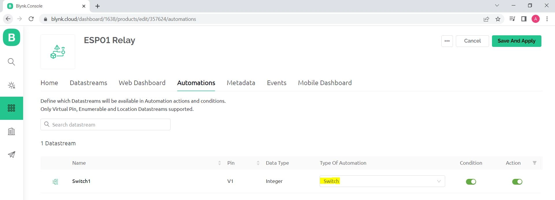
I have added Automation to control the relay automatically as per the pre-defined time.
I have turned on the Condition and Action radio button for the first Datastream V1. The “Type of Automation” will be “Switch”.
Create Web Dashboard in Blynk Cloud
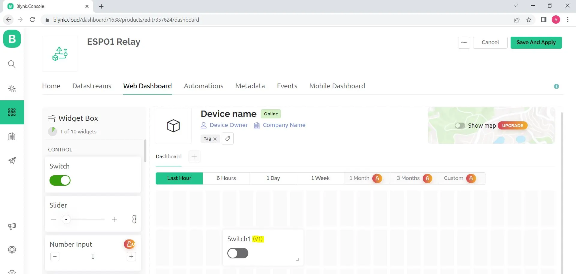
After that, click and drag a Switch widget. Then select the related Datastream for the widget.
Then click on “Save” to save the template.
Add Device in Blynk Cloud using Template
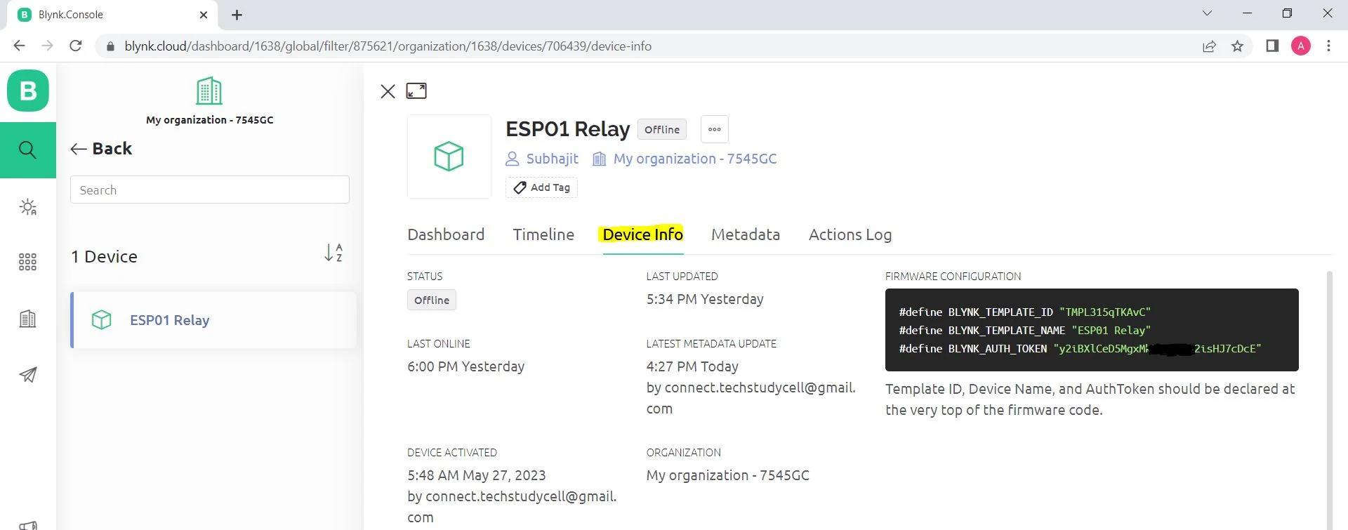
You can refer to the following article to add a device to the Blynk cloud.
Program ESP01 with Arduino IDE
Please refer to this article for Programming ESP-01 using Arduino IDE.
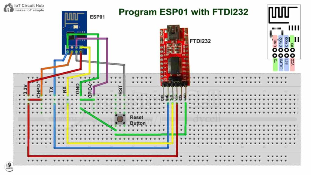
In Arduino IDE, you have to download and install the ESP8266 board and Blynk Library (Version: 1.2.0).
Go to Sketch -> Include Libraries -> Manage Libraries in Arduino IDE, then search “Blynk”.
When you try to install the Blynk library, it may ask you to install all the dependencies. Then Click on Install All.
Source Code for this ESP-01 Project
In the sketch, you have to update only the BLYNK_TEMPLATE_ID, BLYNK_DEVICE_NAME, and Auth Token.
/* Fill-in your Template ID (only if using Blynk.Cloud) */
#define BLYNK_TEMPLATE_ID ""
#define BLYNK_TEMPLATE_NAME ""
#define BLYNK_AUTH_TOKEN ""
Enter the WiFi Credentials.
// Your WiFi credentials.
// Set password to "" for open networks.
char ssid[] = "";
char pass[] = "";
After doing these changes, please upload the code to the ESP-01 module.
Configure the Blynk IoT App for ESP-01 Relay
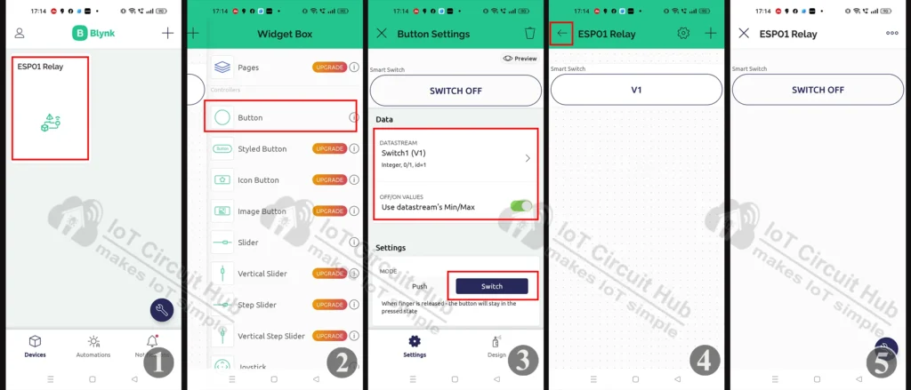
Open the Blynk IoT app then follow these steps:
- Click on the Device Name (ESP01 Relay).
- Go to edit mode, and add a BUTTON widget.
- Tap on the BUTTON widget, select the “V1” Datastream, and “Switch” mode.
- Exit from the edit mode.
- Your mobile dashboard is ready.
PCB for the ESP01 project
To connect the switches with ESP01 GPIOs, you can use the following PCB. Using this PCB, you can connect 2 relays and 2 switches with ESP01.
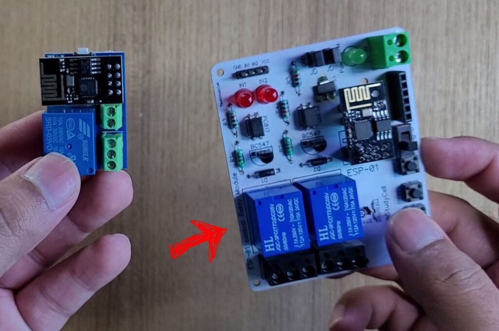
You can order any custom design PCBs from PCBWay at very reasonable prices.

You can also explore different PCB projects from their Open-source community pcbway.com/project/.
In honor of PCBWay’s 9th anniversary, they are offering enticing discounts. Customers now have the opportunity to enjoy exclusive offers and special incentives as a token of gratitude for their ongoing support and to celebrate this remarkable achievement.

Discover a wide range of offerings including free coupons, free modules, special deals, sponsorship, and more. Don’t miss the anniversary sale to experience exceptional savings and witness PCBWay’s industry leadership in PCB fabrication and assembly.
For more details please click here.
Testing the ESP-01 Relay circuit
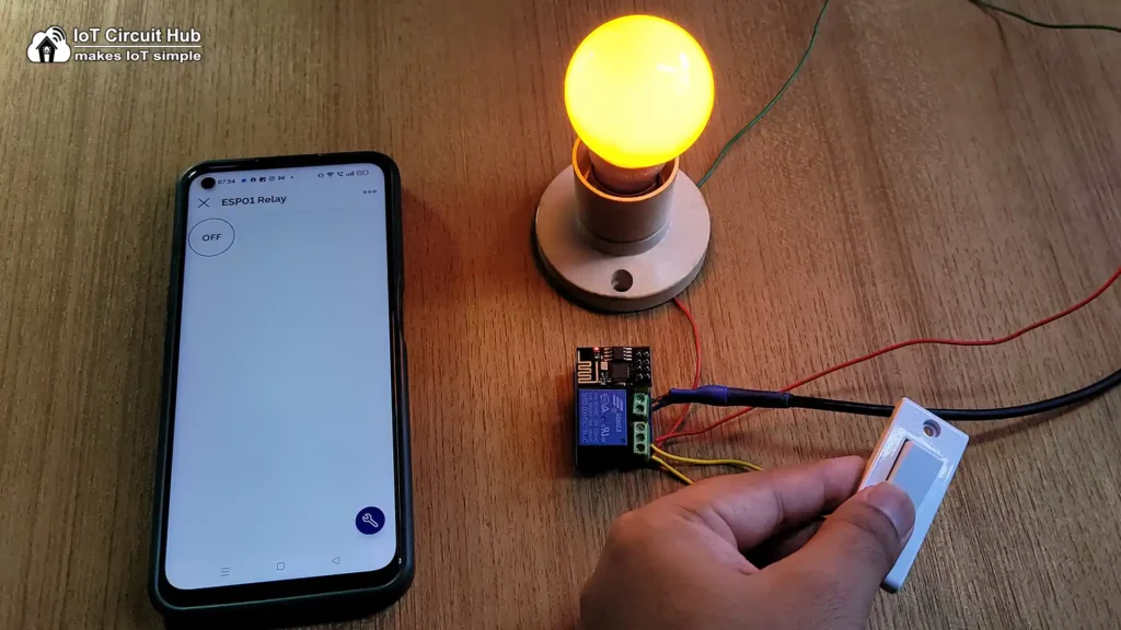
Now connect the ESP01 with the PCB, turn on the supply, and press the reset button.
If the ESP01 is connected to WiFi, you can control the appliances from the Blynk IoT app.
If the WiFi is not available, the relay will turn off, then you can control the lamp manually with the switch.
After testing, place the circuit inside a switch box as shown in the picture.
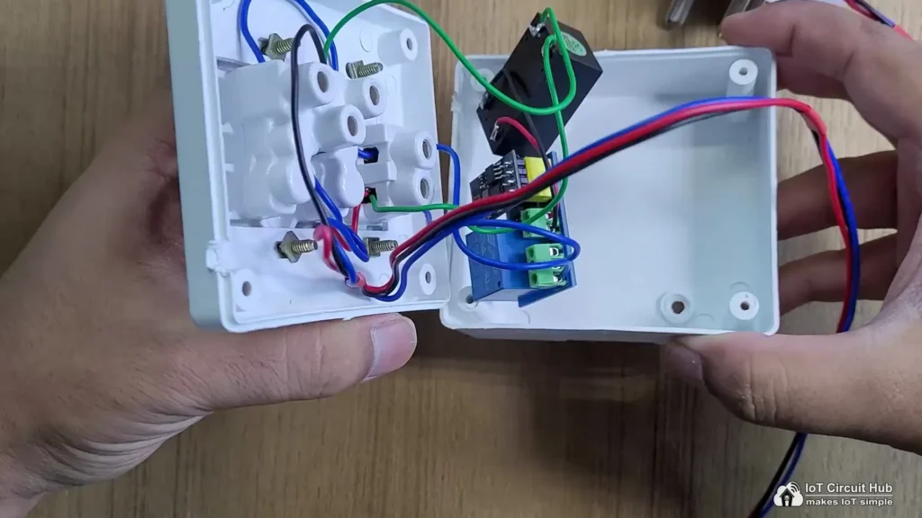
Control any appliances with DIY Smart Switch
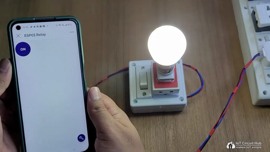
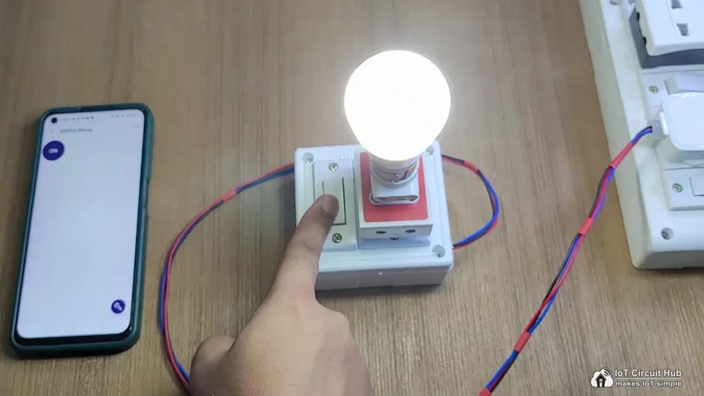
Now you can control any appliances through the internet from anywhere in the world using the Blynk IoT application.
I hope you like this IoT project idea with the new Blynk 2.0 IoT Cloud and ESP-01 ESP8266.
Click Here for more such ESP8266 projects.
Please do share your feedback on this IoT project. Thank you for your time.

