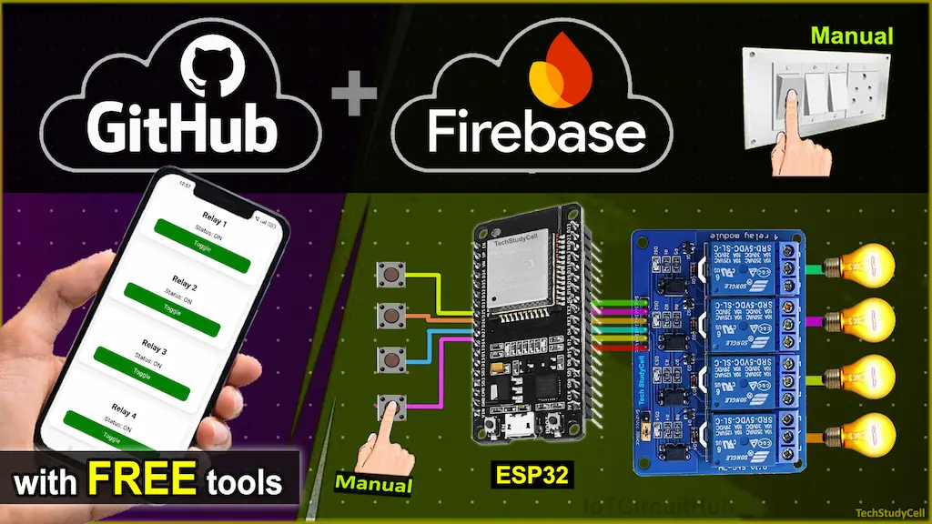
Control your home appliances in real-time from anywhere using ESP32 Firebase Realtime Database, and a responsive Web Dashboard and manual relay control using either push buttons or latched switches.

Table of Contents
Project Overview
This project enables you to:
- Control 4 electrical appliances using relays (active-low).
- Monitor and update relay status using Firebase Realtime Database.
- Use a web dashboard (hosted on GitHub Pages) to control relays from anywhere in the world.
- Add manual control using either push buttons or latched switches.
- Get real-time feedback and sync between the web dashboard and the physical ESP32 board.

How the ESP32 Firebase Project Works
- ESP32 connects to your Wi-Fi router and authenticates with Firebase using the provided credentials.
- On startup, all relays are initialized to OFF (HIGH for active-low relays).
- A web dashboard, deployed on GitHub Pages, updates Firebase when a user toggles a relay switch.
- ESP32 constantly listens for Firebase RTDB updates and changes the relay state accordingly.
- Manual control via physical buttons is handled using the AceButton library:
- Latched switch: Relay stays ON while the switch is pressed and OFF when released.
- Push button: Relay toggles ON/OFF on every release event.
- The current state is written back to the Firebase Realtime Database to keep the system in sync.

Required Components:
Circuit of the ESP32 Web Server project

The circuit is very simple, I have used D23, D19, D18 & D5 GPIO to control the 4-channel relay module.
And, the GPIO D13, D12, D14 & D27 are connected with switches to control the relay module manually.
If you want to use push buttons for manual control, then refer to the following circuit diagram.

I have used the INPUT_PULLUP function in Arduino IDE instead of using the pull-up resistors with each push button.
As per the source code, when the control pins of the relay module receive a LOW signal, the relay will turn on, and the relay will turn off for the HIGH signal in the control pin.
I have used a 5V 5Amp mobile charger to supply the circuit.
Please take proper safety precautions while connecting the AC appliances.
Configure the Firebase for the ESP32
Here are the short steps to configure Firebase for your ESP32 IoT project:
- Create Firebase Project
- Go to Firebase Console
- Click Add project → Follow prompts
- Enable Realtime Database
- In your project dashboard, go to Build > Realtime Database
- Click Create Database
- Choose Start in test mode (or setup rules later)
- Enable Email/Password Authentication
- Go to Build > Authentication > Sign-in method
- Enable Email/Password
- Create a User
- Go to Users tab in Authentication
- Click Add user → Enter email and password
- Get API Key and Database URL
- Go to Project Settings (gear icon) & Create a Web App.
- Under General > Web API Key → Copy it
- Under Realtime Database → Copy the URL
- Modify the Realtime Database Rules
- go to Build > Realtime Database > Rules tab
- Copy and paste the following details:
{
  "rules": {
    ".read": "auth != null",
    ".write": "auth != null"
  }
}
What these rules mean:
.read: Controls who can read data from the database..write: Controls who can write data to the database.auth != null: Only allow access if the user is authenticated (i.e., logged in).
Program ESP32 with Arduino IDE
In the tutorial video, I explained all the steps for programming the NodeMCU using Arduino IDE.
- Update the Preferences –> Aditional boards Manager URLs: https://dl.espressif.com/dl/package_esp32_index.json, http://arduino.esp8266.com/stable/package_esp8266com_index.json
- Then install the ESP32 board (version: 3.2.0) from the Board Manager, or Click Here to download the ESP32 board.
- You need the following libraries:
- Firebase_ESP_Client by Mobizt (version 4.4.17)
- ArduinoJson (version 7.4.1)
- AceButton (version 1.10.1)
Source Code for the ESP32 Firebase Relay Project
To make your ESP32 project work with Wi-Fi and Firebase, you must update the placeholders in your code with your actual credentials.
Here’s what each field means and how to fill it:
Update These Fields in the Code:
// Wi-Fi credentials
const char* ssid = "YourWiFiName";          // 🔹 Your Wi-Fi name (SSID)
const char* password = "YourWiFiPassword";  // 🔹 Your Wi-Fi password

// Firebase credentials
#define API_KEY "YourFirebaseWebAPIKey"          // 🔹 Found in Project Settings > General
#define DATABASE_URL "https://your-project-id.firebasedatabase.app/"  // 🔹 From Realtime Database URL
#define USER_EMAIL "[email protected]"  // 🔹 Firebase Authentication email
#define USER_PASSWORD "your-auth-password"        // 🔹 Firebase Authentication password
📌 Where to find them:
- API_KEY:
- Go to Firebase Console > Your Project > ⚙️ Settings > General.
- Scroll down to “Web API Key”.
- DATABASE_URL:
- Go to Realtime Database in Firebase.
- The URL will look like:
https://your-project-id-default-rtdb.firebasedatabase.app/
- USER_EMAIL / USER_PASSWORD:
- Go to the Authentication tab > Add a new user with email & password.
Detailed line-by-line explanation of the source code:
Include Libraries
#include <WiFi.h>
#include <Firebase_ESP_Client.h>
#include <AceButton.h>
using namespace ace_button;
This section imports the necessary libraries:
WiFi.henables Wi-Fi connectivity.Firebase_ESP_Client.his used for communication with Firebase Realtime Database.AceButton.hsimplifies handling pushbuttons. Theace_buttonnamespace allows direct access to its classes and constants.
Wi-Fi and Firebase Credentials
const char* ssid = "";  //WiFi Name
const char* password = "";  //WiFi Password

#define API_KEY ""
#define DATABASE_URL ""
#define USER_EMAIL ""
#define USER_PASSWORD ""
This block defines placeholders for Wi-Fi credentials and Firebase authentication details like API key, database URL, and login credentials. These need to be filled in for the project to function.
GPIO Pin Definitions
#define RELAY1 23
#define RELAY2 19
#define RELAY3 18
#define RELAY4 5

#define SwitchPin1 13
#define SwitchPin2 12
#define SwitchPin3 14
#define SwitchPin4 27
Relay and button pins are defined here. The relays are connected to GPIOs 23, 19, 18, and 5 (active LOW), and the pushbuttons are connected to GPIOs 13, 12, 14, and 27.
Firebase and Button Instances
FirebaseData fbdo;
FirebaseAuth auth;
FirebaseConfig config;

AceButton button1(SwitchPin1);
AceButton button2(SwitchPin2);
AceButton button3(SwitchPin3);
AceButton button4(SwitchPin4);
This block initializes Firebase objects:
fbdo: for database operationsauth: for user authenticationconfig: for Firebase configuration
It also creates AceButton instances tied to the button pins.
Event Handler Function
void handleEvent(AceButton* button, uint8_t eventType, uint8_t /* buttonState */) {
  int id = button->getPin();
  bool relayState = false;

  switch (id) {
    case SwitchPin1:
      relayState = (eventType == AceButton::kEventPressed);
      digitalWrite(RELAY1, relayState ? LOW : HIGH);
      Firebase.RTDB.setBool(&fbdo, "/relay1", relayState);
      break;
    ...
  }
}
This function handles button press events. When a button is pressed (kEventPressed), it turns ON the respective relay (LOW = ON for active LOW relays). It also updates the relay state in Firebase to keep the cloud state synced.
Setup Function
void setup() {
  Serial.begin(115200);
Initializes the serial monitor for debugging.
  pinMode(RELAY1, OUTPUT);
  ...
  digitalWrite(RELAY1, HIGH);
  ...
Sets relay pins as outputs and initializes them to OFF (HIGH for active LOW logic).
  pinMode(SwitchPin1, INPUT_PULLUP);
  ...
Configures button pins as input with pull-up resistors. This means buttons are active when pulled LOW.
  ButtonConfig* config1 = button1.getButtonConfig();
  ...
  config1->setEventHandler(handleEvent);
  ...
Assigns the handleEvent function to each button to respond to events like press or release.
  WiFi.begin(ssid, password);
  ...
Connects to the specified Wi-Fi network and waits until connected.
  config.api_key = API_KEY;
  ...
  Firebase.begin(&config, &auth);
  Firebase.reconnectWiFi(true);
Sets Firebase credentials and initializes Firebase connection. It also enables automatic reconnection if Wi-Fi disconnects.
Loop Function
void loop() {
  if (Firebase.ready()) {
    ...
    if (Firebase.RTDB.getBool(&fbdo, "/relay1")) {
      r1 = fbdo.boolData();
      digitalWrite(RELAY1, r1 ? LOW : HIGH);
    }
    ...
  }
Checks if Firebase is ready, then reads the current states of all four relays from the database. Based on values (true or false), the respective relays are switched ON (LOW) or OFF (HIGH). This ensures that changes made from the web dashboard are reflected on the ESP32.
  button1.check();
  ...
  delay(10);
Calls check() for each button to detect new button events. The small delay allows for stable button reading.
Deploy Web Dashboard on GitHub Pages
- Create a GitHub account (if not already).
- Create a new repository, e.g.,
esp32-dashboard. - Upload your HTML (index.html) to the repo.
- Go to Settings → Pages.
- Under Source, choose
mainbranch and/ (root)folder. - Click Save – GitHub will generate a public URL like:
https://your-username.github.io/esp32-dashboard/ - Open the URL to view your live dashboard!
About PCBWay and their services
You can order any custom-designed PCBs from PCBWay at very reasonable prices.

PCBWay not only produces FR-4 and Aluminum boards but also advanced PCBs like Rogers, HDI, and Flexible and Rigid-Flex boards, at very affordable prices.
For the online instant quote page please visit – pcbway.com/orderonline
You can also explore different PCB projects from their Open-source community pcbway.com/project/.
Also, during September, there is no extra charge for the purple PCB.
Also, during September, there is no extra charge for the purple PC
Test the ESP32 Firebase Project
Once the project is uploaded:
- Open the Serial Monitor to confirm Wi-Fi and Firebase connections.
- Control relays via:
- Your web dashboard
- The physical push buttons
All changes are reflected in real-time on Firebase!
This process ensures that your ESP32 home automation setup is fully functional and can be controlled both physically and remotely via the Web Dashboard through the internet.
I hope you like this ESP32 Firebase project.
Click Here for more such ESP32 projects.
Please do share your feedback.


