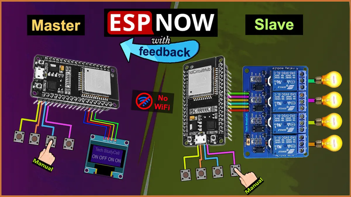
Control multiple relays wirelessly using two ESP32 boards with the ESP-NOW protocol. This ESP32 ESPNOW project demonstrates a Master-Slave configuration, where the Master sends commands to the Slave to control four relays. The system includes real-time feedback on an OLED display, manual button control on both ends, and status indication via the ESP32’s onboard LED.

Table of Contents
Overall Functionality:
- An ESP32 Master has 4 buttons. Each button controls one of the 4 relays on the ESP32 Slave.
- When a button is pressed, the master sends a message (via ESP-NOW) to the slave.
- The slave receives this message and updates the corresponding relay.
- The slave then sends feedback back to the master, containing the current state (ON/OFF) of all relays.
- The master receives the feedback and displays the relay status on an OLED display.

Tutorial Video on ESP32 ESPNOW Project
Required Components
- ESP32 DevKIT V1 Amazon 2 qty
- 4-channel 5V SPDT Relay Module (Active Low) Amazon
- Push Buttons 8 qty
- SSD1306 OLED Display (I2C)
- Jumper Wires
- Breadboard or PCB
Circuit of the ESP32 ESPNOW Relay project
- Master ESP32: Has 4 push buttons to send commands using ESP-NOW and receives feedback to update OLED.
- Slave ESP32: Controls 4 relays, receives commands, and sends feedback to the Master. It also has 4 manual control buttons for local operation.
Master ESP32 Circuit

In the master circuit, GPIO D13, D12, D14, & D27 are connected with push buttons to control relays in the slave circuit.
I have used the INPUT_PULLUP function in Arduino IDE instead of using the pull-up resistors with each push button.
For the OLED, I have used GPIO 21 for SDA and GPIO 22 for SCL pin (I2C).
I have used GPIO 2 (Inbuilt LED) for slave connection indication.
Slave ESP32 Circuit

In the slave circuit, I have used D23, D19, D18 & D5 GPIO pins to control the 4-channel relay module.
The GPIO D13, D12, D14, & D27 are connected with push buttons to control the relay module manually.
I have used the INPUT_PULLUP function in Arduino IDE instead of using the pull-up resistors with each push button.
As per the source code, when the control pins of the relay module receive a LOW signal, the relay will turn on, and the relay will turn off for the HIGH signal in the control pin.
I have used a 5V 5A mobile charger to supply the circuit.
Please take proper safety precautions while connecting the AC appliances.
Program ESP32 with Arduino IDE
In the tutorial video, I have explained all the steps to program the ESP32 using Arduino IDE.
- Update the Preferences –> Aditional boards Manager URLs: https://dl.espressif.com/dl/package_esp32_index.json, http://arduino.esp8266.com/stable/package_esp8266com_index.json
- Then install the ESP32 board from the Board Manager, or Click Here to download the ESP32 board (version 3.2.0).
- Download the required libraries from the following links:
- AceButton version 1.10.1.
- Adafruit_SSD1306 version 2.5.13.
- Adafruit Unified Sensor version 1.1.15.
Source Codes for the ESP-NOW ESP32 project
First, you have to get the MAC addresses of both the master and slave ESP32.
Master ESP32 Code Guide
Master ESP32 code sends button states to a slave ESP32 and receives feedback with relay statuses.
Here you have to enter the MAC address of the slave ESP32 (as shown).
Here’s a detailed line-by-line explanation of your ESP32 Master code:
1. Libraries and Setup
#include <WiFi.h>
#include <esp_now.h>
#include <Wire.h>
#include <Adafruit_SSD1306.h>
#include <AceButton.h>
- WiFi.h and esp_now.h: Used to enable ESP-NOW communication.
- Wire.h: Enables I2C communication, used for OLED.
- Adafruit_SSD1306.h: Library to control the OLED display.
- AceButton.h: Makes it easier to detect button events like press, release, long press, etc.
2. OLED Display Configuration
#define SCREEN_WIDTH 128
#define SCREEN_HEIGHT 32
#define OLED_RESET -1
Adafruit_SSD1306 display(SCREEN_WIDTH, SCREEN_HEIGHT, &Wire, OLED_RESET);
- Defines the OLED size and creates a display object.
-1means no reset pin is used.
3. GPIO and Button Configuration
#define LED_BUILTIN 2
const int buttonPins[] = {13, 12, 14, 27};
const int numButtons = 4;
bool buttonStates[numButtons] = {false, false, false, false};
LED_BUILTIN: GPIO 2 is used as a status LED.buttonPins: Array of GPIO pins connected to buttons.buttonStates: Tracks current ON/OFF state for each button.
4. ESP-NOW Data Structures
uint8_t slaveMAC[] = {0x24, 0xD7, 0xEB, 0x14, 0xE2, 0xBC};
- Replace with your actual slave MAC address.
typedef struct {
  int buttonID;
  bool state;
} ButtonData;

typedef struct {
  bool relayStates[4];
} FeedbackData;
ButtonData: Sent from Master ➝ Slave when a button is pressed.FeedbackData: Sent from Slave ➝ Master with current relay states.
ButtonData buttonData;
FeedbackData feedbackData;
- Creates actual variables to use the structures.
5. Connection and Feedback Tracking
bool slaveConnected = false;
unsigned long lastFeedbackTime = 0;
const unsigned long feedbackTimeout = 4000;
slaveConnected: Flag to know if the slave is responding.lastFeedbackTime: Time when last feedback was received.feedbackTimeout: If feedback isn’t received for 4 seconds, assume disconnected.
6. AceButton Setup
AceButton buttons[numButtons] = {
  AceButton(buttonPins[0]),
  AceButton(buttonPins[1]),
  AceButton(buttonPins[2]),
  AceButton(buttonPins[3])
};
- Creates an AceButton object for each button pin.
7. ESP-NOW Send Callback
void onDataSent(const uint8_t *mac_addr, esp_now_send_status_t status) {
  slaveConnected = (status == ESP_NOW_SEND_SUCCESS);
  digitalWrite(LED_BUILTIN, slaveConnected ? HIGH : LOW);
- Called after the data is sent to the slave.
- Updates LED and flag based on whether the send was successful.
8. ESP-NOW Receive Callback
void onDataRecv(const esp_now_recv_info_t *info, const uint8_t *incomingData, int len)
- Called when data is received from the slave.
  memcpy(&feedbackData, incomingData, sizeof(feedbackData));
  lastFeedbackTime = millis();
- Copies the data into
feedbackData. - Updates the time so we know slave is alive.
  // Serial and OLED display update
  for (int i = 0; i < 4; i++) {
    Serial.print(feedbackData.relayStates[i] ? "ON " : "OFF ");
  }
- Prints current relay states to serial and updates the OLED.
9. Button Press Handler
void handleButtonPress(AceButton *button, uint8_t eventType, uint8_t buttonState)
- Called when a button is released.
if (eventType == AceButton::kEventReleased) {
- Only reacts to button release events.
    for (int i = 0; i < numButtons; i++) {
      if (buttonPins[i] == buttonIndex) {
        buttonStates[i] = !buttonStates[i]; // Toggle the state
        buttonData.buttonID = i;
        buttonData.state = buttonStates[i];
        esp_now_send(slaveMAC, (uint8_t *)&buttonData, sizeof(buttonData));
- Identifies which button was pressed, toggles its state, and sends the info to the slave.
10. setup() Function
void setup() {
  Serial.begin(115200);
- Start serial communication for debugging.
  if (!display.begin(SSD1306_SWITCHCAPVCC, 0x3C)) {
    Serial.println(F("SSD1306 allocation failed"));
- Initializes the OLED display at I2C address
0x3C.
  for (int i = 0; i < numButtons; i++) {
    pinMode(buttonPins[i], INPUT_PULLUP);
    buttons[i].setEventHandler(handleButtonPress);
  }
- Sets button pins as inputs with internal pull-up and assigns event handler.
  WiFi.mode(WIFI_STA);
  if (esp_now_init() != ESP_OK) {
    Serial.println("ESP-NOW init failed");
    return;
  }
- Puts ESP32 into station mode and starts ESP-NOW.
  esp_now_register_send_cb(onDataSent);
  esp_now_register_recv_cb(onDataRecv);
- Registers callbacks for send and receive.
  esp_now_peer_info_t peerInfo = {};
  memcpy(peerInfo.peer_addr, slaveMAC, 6);
  peerInfo.channel = 0;
  peerInfo.encrypt = false;
  esp_now_add_peer(&peerInfo);
- Adds the slave as a peer so we can communicate with it via ESP-NOW.
  pinMode(LED_BUILTIN, OUTPUT);
  digitalWrite(LED_BUILTIN, LOW);
- Configures the built-in LED pin.
11. loop() Function
  for (int i = 0; i < numButtons; i++) {
    buttons[i].check();
  }
- Constantly checks all buttons for events.
  if (millis() - lastFeedbackTime >= feedbackTimeout) {
    digitalWrite(LED_BUILTIN, LOW);
  } else {
    digitalWrite(LED_BUILTIN, HIGH);
  }
- If feedback is not received in 4 seconds → turn off the LED (assume disconnected).
- If feedback is recent → keep LED on.
Summary of What’s Happening in Master’s code
| Component | Role |
|---|---|
| Master Buttons | Send ON/OFF state to Slave |
| Slave | Controls relays, sends back feedback |
| OLED Display | Shows current state of 4 relays like: ON OFF OFF ON |
| Built-in LED | Shows connection status. ON = Slave alive, OFF = no response for 4s |
| AceButton | Makes button handling easy |
| ESP-NOW | Handles communication wirelessly without WiFi |
Slave ESP32 Code Guide
This code handles 4 relays, receives control commands from the master ESP32, sends feedback, and also allows manual control using buttons.
In this sketch, you have to enter the MAC address of the master ESP32 (as shown).
Here’s the breakdown:
Include Required Libraries
#include <WiFi.h>
#include <esp_now.h>
#include <AceButton.h>WiFi.h: Required to set ESP32 to station mode.esp_now.h: Enables the ESP-NOW communication.AceButton.h: A reliable button library for debouncing and handling events.
Use AceButton Namespace
using namespace ace_button;- Simplifies code by allowing direct use of
AceButtonclasses/functions without prefixingace_button::.
Relay and Button Setup
const int relayPins[] = {23, 19, 18, 5};
const int numRelays = 4;
bool relayStates[numRelays] = {false, false, false, false};

const int buttonPins[] = {13, 12, 14, 27};relayPins[]: GPIOs connected to relays (active-low relays).relayStates[]: Keeps track of current relay states (true= ON,false= OFF).buttonPins[]: GPIOs connected to manual push-buttons.
Create AceButton Objects
AceButton buttons[numRelays] = {
  AceButton(buttonPins[0]), AceButton(buttonPins[1]),
  AceButton(buttonPins[2]), AceButton(buttonPins[3])
};- Creates 4 AceButton instances mapped to the button pins.
Data Structures
typedef struct {
  int buttonID;
  bool state;
} ButtonData;

typedef struct {
  bool relayStates[numRelays];
} FeedbackData;ButtonData: Used to receive control command from the master (which button,what state).FeedbackData: Used to send current relay states back to the master.
Connection & Data Buffers
ButtonData buttonData;
FeedbackData feedbackData;
bool masterConnected = false;
uint8_t masterMAC[] = {0xC0, 0x49, 0xEF, 0xD1, 0x25, 0x4C};- Buffers for sending/receiving data.
masterMAC: MAC address of the master ESP32 (this needs to match your actual master MAC).
Callback: On Data Received
void onDataRecv(const esp_now_recv_info_t *info, const uint8_t *incomingData, int len) {
memcpy(&buttonData, incomingData, sizeof(buttonData));- Fills
buttonDatawith received command (button ID and state).
  int relayIndex = buttonData.buttonID;
  if (relayIndex >= 0 && relayIndex < numRelays) {
    relayStates[relayIndex] = buttonData.state;
    digitalWrite(relayPins[relayIndex], relayStates[relayIndex] ? LOW : HIGH);
    sendFeedbackToMaster();
  }
}- Updates the relay state and GPIO pin.
- Sends updated states back to the master.
Callback: On Data Sent
void onDataSent(const uint8_t *mac_addr, esp_now_send_status_t status) {
  masterConnected = (status == ESP_NOW_SEND_SUCCESS);
}- Updates
masterConnectedto reflect if the last message was successfully sent.
Send Feedback to Master
void sendFeedbackToMaster() {
  memcpy(feedbackData.relayStates, relayStates, sizeof(feedbackData.relayStates));
esp_now_send(masterMAC, (uint8_t *)&feedbackData, sizeof(feedbackData));- Sends current relay states to the master.
  Serial.print("Sending feedback to master: ");
  for (int i = 0; i < 4; i++) {
    Serial.print(feedbackData.relayStates[i] ? "ON " : "OFF ");
  }
  Serial.println();
}- Serial monitor shows which states are being sent.
Button Press Handler
void handleButtonPress(AceButton *button, uint8_t eventType, uint8_t buttonState) {
  if (eventType == AceButton::kEventReleased) {
int buttonIndex = button->getPin();- Only reacts on button release to avoid toggling too quickly.
    for (int i = 0; i < numRelays; i++) {
      if (buttonPins[i] == buttonIndex) {
        relayStates[i] = !relayStates[i];
digitalWrite(relayPins[i], relayStates[i] ? LOW : HIGH);- Finds which button was pressed, and toggles the corresponding relay.
        if (masterConnected) {
          sendFeedbackToMaster();
        }
        break;
      }
    }
  }
}- If the master is connected, it sends the updated state back immediately.
Setup Function
void setup() {
Serial.begin(115200);- Starts Serial for debugging.
  for (int i = 0; i < numRelays; i++) {
    pinMode(relayPins[i], OUTPUT);
    digitalWrite(relayPins[i], HIGH);  // OFF (active low)
}- Relay pins are set as outputs and initially OFF.
  ButtonConfig *buttonConfig = ButtonConfig::getSystemButtonConfig();
buttonConfig->setEventHandler(handleButtonPress);- Configures the button system globally with the
handleButtonPress()handler.
  for (int i = 0; i < numRelays; i++) {
    pinMode(buttonPins[i], INPUT_PULLUP);
    buttons[i].getButtonConfig()->setEventHandler(handleButtonPress);
}- Configures each button pin and assigns the handler.
Initialize ESP-NOW
  WiFi.mode(WIFI_STA);
  if (esp_now_init() != ESP_OK) {
    Serial.println("ESP-NOW init failed");
    return;
}- ESP-NOW runs in
WIFI_STAmode. - Initializes ESP-NOW. If it fails, it prints error.
  esp_now_register_recv_cb(onDataRecv);
esp_now_register_send_cb(onDataSent);- Registers callbacks for receive and send.
  esp_now_peer_info_t peerInfo = {};
  memcpy(peerInfo.peer_addr, masterMAC, 6);
  peerInfo.channel = 0;
  peerInfo.encrypt = false;
  if (esp_now_add_peer(&peerInfo) != ESP_OK) {
    Serial.println("Failed to add peer");
  }
}- Registers the master ESP32 as a known peer.
Loop Function
void loop() {
  for (int i = 0; i < numRelays; i++) {
    buttons[i].check();
}- Calls
.check()to handle button events.
  static unsigned long lastFeedbackTime = 0;
  if (millis() - lastFeedbackTime >= 2000) {
    lastFeedbackTime = millis();
    sendFeedbackToMaster();  // Send the relay states to master every 2 seconds
  }
}- Even if no button is pressed, feedback is sent every 2 seconds.

🎉 PCBWay is celebrating its 11th Anniversary — and you’re invited! Join the celebration from June 18 to July 18, 2025, and unlock rewards, coupons, and a chance to win exciting prizes.

🔓 Event Rules: Complete any of 6 simple tasks — like reading their letter, watching a video, placing an order, or uploading a project — to unlock cards. Collect all 6 cards to earn an extra lucky draw chance!
Be part of PCBWay’s journey of innovation and sustainability. Explore Now
Testing the ESP-NOW ESP32 circuit

To avoid any loose connections, I have used PCBs for this project.
ESP-NOW Communication Range (Master-Slave Distance)
The range between the ESP32 master and slave depends on several factors like power level, antenna quality, physical obstructions, and interference.
Typical Range Estimates:
| Environment | Estimated Range |
|---|---|
| Indoor (with walls) | 20 to 50 meters (65 to 164 feet) |
| Open Line of Sight (no obstacles) | 100 to 150 meters (328 to 492 feet) |
| With External Antenna ESP32 | Up to 250+ meters (820+ feet) |
Factors That Affect Range:
- Walls and obstacles (especially concrete or metal)
- Interference from Wi-Fi routers, Bluetooth, or microwave ovens
- Power supply stability
- Type of ESP32 board (some have ceramic antennas, others support external antennas)
Applications of this ESP32 Project
Here are some real-world applications of your ESP-NOW relay control project:
- 🔌 Home Automation – Control lights, fans, appliances wirelessly
- 🚜 Smart Agriculture – Switch irrigation pumps remotely
- 🏠 Remote Gate/Lock Control – Open/close gates without internet
- 🏭 Industrial Machine Control – Operate machinery wirelessly on-site
- 🧯 Fire/Alarm Systems – Trigger alarms or emergency relays
- 🏕️ Off-Grid Automation – Relay control in remote, no-internet areas
- 🚦 Traffic Systems – Control signals or roadside systems wirelessly
I hope you like this ESP32 ESP-NOW project.
Click Here for more such ESP32 projects.
Please do share your feedback.


