Home automation is one of the most popular applications of IoT technology, and with Firebase Home Automation, you can securely monitor and control your devices from anywhere in the world. Unlike traditional DIY smart home projects that work only within a local WiFi network, Firebase provides a cloud-based platform for real-time control and status updates.

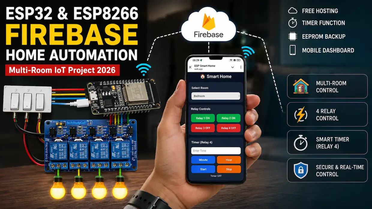
In this project, we will build a powerful Multi-Room Home Automation System using ESP32, ESP8266, Firebase Realtime Database, and Firebase Hosting. The system supports multiple rooms, multiple ESP devices, real-time relay control, timer automation, manual switches, EEPROM backup, and secure user authentication.

The dashboard is hosted for free using Firebase Hosting and can be accessed from any smartphone, tablet, or computer without installing a dedicated mobile application.
Table of Contents
Tutorial Video on Firebase Home Automation Project
Project Overview
The system is designed around Firebase Realtime Database, which acts as a cloud communication bridge between ESP devices and the web dashboard.
Each ESP32 or ESP8266 is assigned to a specific room such as:
- Bedroom
- Kitchen
- Living Room
- Office
- Garage
A single dashboard can control multiple rooms and multiple devices simultaneously.
The project supports both ESP32 and ESP8266, making it suitable for small and large smart home installations.

How the Firebase Home Automation Project Works
The complete system operates using real-time communication between the dashboard and Firebase.
Step 1: ESP Connects to WiFi
When powered on, the ESP32 or ESP8266 connects to the configured WiFi network.
Step 2: Firebase Authentication
After connecting to WiFi, the device securely logs into Firebase using Email/Password Authentication.
Step 3: Room Registration
Each device is assigned to a room path inside Firebase.
Example:
rooms/
   bedroom/
   kitchen/
   office/
Step 4: Dashboard Sends Commands
The dashboard writes relay and timer commands to Firebase Realtime Database.
Step 5: ESP Reads Commands
The ESP continuously checks Firebase and executes the received commands.
Step 6: Status Feedback
After the action is performed, the ESP updates Firebase with the latest relay status.
Step 7: Dashboard Updates
The dashboard instantly displays the updated status, creating real-time synchronization between cloud and hardware.
Required Components for IoT Project
- ESP8266 NodeMCU or ESP32 WiFi module
- 4-channel relay module
- Latched switches or Push buttons

Circuit of the ESP32 control Relays

The circuit is very simple, I have used D23, D19, D18 & D5 GPIO to control the 4-channel relay module.
And, the GPIO D13, D12, D14 & D27 are connected with switches to control the relay module manually.
Here, I have also connected an indicator LED for the timer (in series 220 ohm resistor) with GPIO 15. This is optional.
If you want to use push buttons for manual control, then refer to the following circuit diagram.

I have used the INPUT_PULLUP function in Arduino IDE instead of using the pull-up resistors with each push button.
As per the source code, when the control pins of the relay module receive a LOW signal, the relay will turn on, and the relay will turn off for the HIGH signal in the control pin.
I have used a 5V 5Amp mobile charger to supply the circuit.
Please take proper safety precautions while connecting the AC appliances.
Circuit of the ESP8266 NodeMCU control Relays

In the circuit, I have used D1 (GPIO-5), D2 (GPIO-4), D5 (GPIO-14), and D6 (GPIO-12) GPIO pins to control the 4-channel relay module.
And the GPIO SD3 (GPIO-10), D3 (GPIO-0), D7 (GPIO-13), and RX (GPIO-3) are connected with the pushbuttons to control the relay module manually.
Here, I will use both the built-in LEDs (GPIO 2 & GPIO 16) for the Timer and WiFi indicator.
For the NodeMCU, I will not recommend latched switches for manual control due to some GPIO limitations.
Configure the Firebase for the ESP32/ESP8266
Here are the short steps to configure Firebase for your ESP32 IoT project:
- Create Firebase Project
- Go to Firebase Console
- Click Add project → Follow prompts
- Enable Realtime Database
- In your project dashboard, go to Build > Realtime Database
- Click Create Database
- Choose Start in test mode (or setup rules later)
- Enable Email/Password Authentication
- Go to Build > Authentication > Sign-in method
- Enable Email/Password
- Create a User
- Go to Users tab in Authentication
- Click Add user → Enter email and password
- Get API Key and Database URL
- Go to Project Settings (gear icon) & Create a Web App.
- Under General > Web API Key → Copy it
- Under Realtime Database → Copy the URL
- Modify the Realtime Database Rules
- go to Build > Realtime Database > Rules tab
- Copy and paste the following details:
{
  "rules": {
    ".read": "auth != null",
    ".write": "auth != null"
  }
}
What these rules mean:
.read: Controls who can read data from the database..write: Controls who can write data to the database.auth != null: Only allow access if the user is authenticated (i.e., logged in).
Now, if you want only a specific authenticated user to log in, then get the UID for that user, and copy and paste the following details:
{
  "rules": {
    ".read": "auth.uid === 'YOUR_USER_UID'",
    ".write": "auth.uid === 'YOUR_USER_UID'"
  }
}
Here, you have to enter the UID of the user in the place of YOUR_USER_UID.
Please refer to the tutorial video.
Firebase Database Structure
The project uses a room-based database architecture.
{
  "rooms": {
    "bedroom": {
      "relay1": false,
      "relay2": false,
      "relay3": false,
      "relay4": false,
      "timerActive": false,
      "remaining": 0,
      "statusRequest": false,
      "statusReply": false,
      "deviceStatus": "Disconnected"
    }
  }
}
This structure allows multiple rooms to be added easily without modifying the overall dashboard design.
After downloading the JSON file, unzip it, then click on the 3-dot icon and select import JSON.

Then drag and drop the JSON file and click on import to create the complete database structure.

PCBWay – One-Stop PCB Manufacturing & Assembly Solution
Now PCBWay celebrates its 12th Anniversary! Join the month-long anniversary celebration from July 1 – July 31, 2026, and enjoy big coupons, premium gifts, and exclusive solder mask color perks.

Whether you’re building prototypes or producing PCBs in volume, this is the perfect time to save more on your next project. Don’t miss these limited-time anniversary rewards—visit PCBWay today and take advantage of the special offers before the event ends!
For more details: PCBWay 12th Anniversary
Program ESP32/ESP8266 with Arduino IDE
In the tutorial video, I explained all the steps for programming the ESP32 and NodeMCU using Arduino IDE.
- Update the Preferences –> Aditional boards Manager URLs: https://dl.espressif.com/dl/package_esp32_index.json, http://arduino.esp8266.com/stable/package_esp8266com_index.json
- Then install the ESP32 board (version: 2.0.14) from the Board Manager, or Click Here to download the ESP32 board.
- Then install the ESP8266 board (version: 3.1.2) from the Board Manager, or Click Here to download the ESP8266 board.
- You need the following libraries:
- Firebase_ESP_Client by Mobizt (version 4.4.17)
- ArduinoJson (version 7.4.1)
Source Code for the ESP32 & ESP8266 Firebase Relay Project
To make your Firebase home automation project work with Wi-Fi and Firebase, you must update the placeholders in your code with your actual credentials.

Here’s what each field means and how to fill it
// WiFi
#define WIFI_SSID       "YOUR_WIFI"
#define WIFI_PASSWORD   "YOUR_PASSWORD"

// Firebase
#define API_KEY         "YOUR_API_KEY"
#define DATABASE_URL    "https://your-project-default-rtdb.firebasedatabase.app/"
#define USER_EMAIL      "YOUR_EMAIL"
#define USER_PASSWORD   "YOUR_PASSWORD"
📌 Where to find them:
- API_KEY:
- Go to Firebase Console > Your Project > ⚙️ Settings > General.
- Scroll down to “Web API Key”.
- DATABASE_URL:
- Go to Realtime Database in Firebase.
- The URL will look like:
https://your-project-id-default-rtdb.firebasedatabase.app/
- USER_EMAIL / USER_PASSWORD:
- Go to the Authentication tab > Add a new user with email & password.
// Room Path
String ROOM = "/rooms/bedroom";
Mention the room where the ESP32/ ESP8266 is in, the room name must be the same as the names mentioned in the database structure and index.html.
// Flags
#define USE_EEPROM         1    //1=enable, 0=disable
#define RELAY_ACTIVE_LOW   1    //1=active low relay, 0=active high relay
#define USE_LATCHED_SWITCH 1    //1 = latched switch, 0 = pushbutton
You can also modify these flags as per your circuits.
Now, if you want to use ESP32, then uncomment the GPIO block for ESP32
//================ GPIO ESP32 =================
// Relays
#define RELAY1 23
#define RELAY2 19
#define RELAY3 18
#define RELAY4 5

// Switches
#define SwitchPin1 13
#define SwitchPin2 12
#define SwitchPin3 14
#define SwitchPin4 27

// LEDs
#define TIMER_LED     15
#define WIFI_LED      2
Or, if you want to use ESP8266, then uncomment the GPIO block for ESP8266. And comment the ESP32 GPIO block.
================ GPIO ESP8266 =================
// Relays
#define RELAY1 5   //D1
#define RELAY2 4  //D2
#define RELAY3 14 //D5
#define RELAY4 12 //D6

// Switches
#define SwitchPin1 10  //SD3
#define SwitchPin2 0  //D3 (Should not connect with GND during booting)
#define SwitchPin3 13 //D7
#define SwitchPin4 3  //RX

// LEDs
#define TIMER_LED     2
#define WIFI_LED      16
Now we can program the ESP32 or ESP8266 using Arduino IDE.
Deploy Web Dashboard on Firebase Hosting
First, update the credentials in the index.html

Check the room name mentioned in the HTML (room names must be the same in code, database, and HTML)

Please refer to the following article for a step-by-step guide to deploy the web-dashboard HTML (index.html) on Firebase Hosting for FREE.
Steps to deploy HTML files on Firebase hosting

Test the Firebase Home Automation Project

Once the project is uploaded:
- Open the Serial Monitor to confirm Wi-Fi and Firebase connections.
- Control relays via:
- Your web dashboard
- The physical push buttons or switches

All changes are reflected in real-time on Firebase
Conclusion
This ESP32 & ESP8266 Firebase Home Automation Project demonstrates how to build a modern cloud-based smart home system using low-cost hardware and free Firebase services. With support for multiple rooms, multiple devices, timer automation, real-time synchronization, EEPROM backup, and secure authentication, it provides a robust foundation for advanced IoT applications.
Whether you are a beginner exploring IoT or an experienced maker building a scalable smart home solution, this project offers an excellent combination of functionality, flexibility, and ease of deployment.


