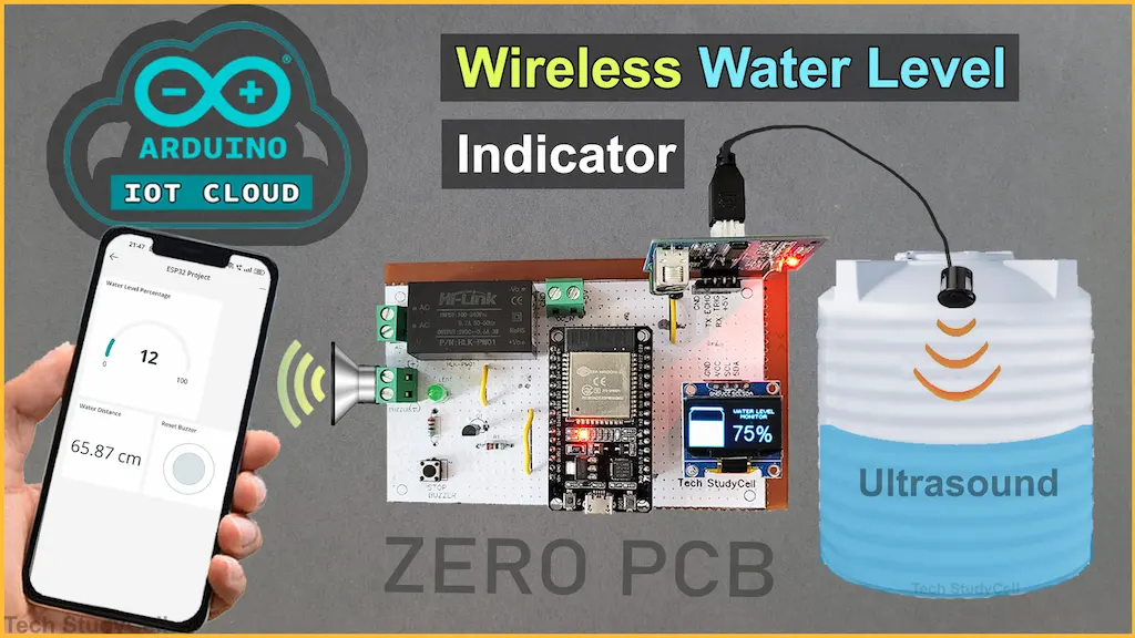
In this IoT (Internet of Things) project, I demonstrate how to create a basic water level indicator using an ESP32, ultrasonic sensor, and the Arduino IoT Cloud platform.


The buzzer will start for the LOW water level, and you can also monitor the water level on the Arduino IoT Remote app through the internet. Also, you can monitor the water tank level on OLED.
The alarm will also start when the tank is full. You press the push button to stop the alarm.
So if you follow all the steps, you can easily make this IoT-based water level monitoring system using ESP32 and Arduino IoT Cloud.
Table of Contents
Required Components for ESP32 Water Level Indicator

- ESP32 DEV KIT V1
- SR04M waterproof ultrasonic sensor OR HC-SR04 sensor
- 0.96″ I2C OLED Display
- 220-ohm 0.25watt Resistors – 2 no
- BC547 NPN Transistor
- LED 5mm – 1no
- 2-pin Push Button
- 2-pin Terminal connectors (3 no)
- 5V DC Buzzer
- AC to DC converter PM01 5V (Optional)
Circuit of ESP32 Water Level Indicator

In the circuit, if you want to use AC voltage, you will need to incorporate a PM01 AC-to-DC converter. Alternatively, you can directly supply 5V DC power to the circuit.
The GPIO D26 & D27 are connected with the Echo & TREG pins of the SR04M-2 waterproof ultrasonic sensor.
The OLED SDA & SCL pins are connected with the D21 & D22 GPIO of ESP32.
GPIO D12 is connected with the push button to stop the buzzer. I have used the INPUT_PULLUP function in Arduino IDE instead of using the pull-up resistors with the push button.
And the indicator LED and Buzzer are connected with GPIO D14 & D13 of ESP32.
You can use any other ultrasonic sensor.

The minimum distance between the sensor and the full tank water level must be greater than 25cm.
PCB Layout for Water Level Sensor
Please download the PCB layout, then print it on the A4 page.
Please check the PCB size while printing, it should be the same as mentioned in the Layout.
Homemade PCB for the Water Level Indicator

In the tutorial video, I have explained, how you can easily make the complete circuit on zero PCB using the PCB Layout.
Tutorial video on ESP32 Water Level Detector
During the tutorial video on ultrasonic water level indicator, I covered the following topics:
- Quick demo on IoT-based water level monitoring system.
- How to make the water level detector on Zero PCB.
- Set up the Arduino IoT Cloud for ESP32.
- Source code for the IoT-based water level sensor.
- Monitor the water level on the Arduino IoT Remote app.
PCB for this ESP32 Water Level Indicator
You can also download the PCB Gerber file and order the PCB from PCBWay.

About PCBWay and its services
You can also use this PCB for this ESP32 IoT project. Just download the Gerber file and order the PCB from PCBWay.
You can order any custom-designed PCBs from PCBWay at very reasonable prices.

PCBWay not only produces FR-4 and Aluminum boards but also advanced PCBs like Rogers, HDI, and Flexible and Rigid-Flex boards, at very affordable prices.
For the online instant quote page please visit – pcbway.com/orderonline
You can also explore different PCB projects from their Open-source community pcbway.com/project/.
For more details please visit the following articles.
Why PCBway
Arduino IoT Cloud FREE account setup
For this IoT project, I have used the Arduino Cloud Free plan.

First, sign up for the Arduino IoT Cloud platform.
Then create a Thing and associate the ESP32 device with the Thing. You can refer to the following Arduino Cloud tutorial.
Getting Started with Arduino IoT
After creating the Thing, we have to add three cloud variables.

- First Variable name: waterLevelPercentage
- Variable Type: Integer
- Variable Permission: Read Only (as it will only show the reading).
- Variable Update Policy: Periodically (Every 2s).

- Second Variable name: “waterDistance“.
- Variable Type: String.
- Variable Permission: Read Only (as it will only show the reading).
- Variable Update Policy: Periodically (Every 2s).

- Third Variable name: “buzzerState“.
- Variable Type: Boolean.
- Variable Permission: Read & Write.
- Variable Update Policy: On change.

Then create the Dashboard with the following widgets.

- For the waterLevelPercentage variable: Gauge widget (Min value 0 & Max value 100)
- waterDistance variable: Value widget
- buzzerState variable: Push Button widget
Program ESP32 with Arduino IDE
In the tutorial video, I have explained all the steps to program the ESP32 using Arduino IDE.
- Update the Preferences –> Aditional boards Manager URLs: https://dl.espressif.com/dl/package_esp32_index.json, http://arduino.esp8266.com/stable/package_esp8266com_index.json
- Then install the ESP32 board from the Board Manager or Click Here to download the ESP32 board.
- Download the required libraries from the following links:
- ArduinoIoTCloud version 1.0.2 by Arduino and all the dependencies.
- Adafruit_SSD1306 version 2.5.13.
Go to Sketch -> Include Libraries -> Manage Libraries in Arduino IDE.

When you try to install the ArduinoIoTCloud library, it will ask you to install all the dependencies. Then Click on Install All.
Code for Arduino IoT Cloud ESP32 Water Level indicator
In the sketch, you have to update the following details.
// Arduino IoT Cloud Device credentials
const char DEVICE_ID[] = "";  // Replace with your device ID
const char SECRET_KEY[] = "";// Replace with your secret key
Enter the WiFi Credentials.
// WiFi credentials
const char SSID[]     = ""; // Replace with your WiFi SSID
const char PASS[]     = "";  // Replace with your WiFi password
Define Water Level Distance for empty tank and full tank in CM.
// Tank distance thresholds (in cm)
const int emptyTankDistance = 70;
const int fullTankDistance = 30;
Define trigger value in percentage, alarm will start when the water level drops below triggerPer.
// Trigger percentage for alarm
const int triggerPer = 10;
Here I have defined the triggerPer 10%, but you can define any value like 5%, 20% etc.

The ESP32 will only calculate the water level if the measured distance is between the empty tank distance and the full tank distance.
After making these changes, please upload the code to ESP32.
Here’s a line-by-line explanation of the code:
1. Include Libraries
#include <WiFi.h>
#include <ArduinoIoTCloud.h>
#include <Arduino_ConnectionHandler.h>
#include <Adafruit_SSD1306.h>
WiFi.h: Enables Wi-Fi connectivity for the ESP32.ArduinoIoTCloud.h: Provides functionality to interact with the Arduino IoT Cloud.Arduino_ConnectionHandler.h: Manages the connection to the Arduino IoT Cloud.Adafruit_SSD1306.h: Allows control of the SSD1306 OLED display.
2. Define Wi-Fi and Arduino IoT Cloud Credentials
const char SSID[]     = "";        // Replace with your WiFi SSID
const char PASS[]     = "";    // Replace with your WiFi password
const char DEVICE_ID[] = "";  // Replace with your device ID
const char SECRET_KEY[] = "";// Replace with your secret key
SSID: Your Wi-Fi network name.PASS: Your Wi-Fi password.DEVICE_ID: Unique identifier for your device in the Arduino IoT Cloud.SECRET_KEY: Security key for authenticating your device with the Arduino IoT Cloud.
3. Declare Cloud-Synced Variables
int waterLevelPercentage;
String waterDistance;
bool buzzerState;
waterLevelPercentage: Stores the water level as a percentage.waterDistance: Stores the distance measured by the ultrasonic sensor as a string.buzzerState: Tracks whether the buzzer is ON or OFF.
4. OLED Display Configuration
#define SCREEN_WIDTH 128 // OLED display width, in pixels
#define SCREEN_HEIGHT 32 // OLED display height, in pixels
#define OLED_RESET     -1 // Reset pin # (or -1 if sharing Arduino reset pin)
Adafruit_SSD1306 display(SCREEN_WIDTH, SCREEN_HEIGHT, &Wire, OLED_RESET);
SCREEN_WIDTHandSCREEN_HEIGHT: Define the dimensions of the OLED display.OLED_RESET: Specifies the reset pin for the OLED display.Adafruit_SSD1306 display(...): Initializes the OLED display object.
5. Cloud Connection Handler
WiFiConnectionHandler ArduinoIoTPreferredConnection(SSID, PASS);
WiFiConnectionHandler: Manages the Wi-Fi connection using the provided SSID and password.
6. GPIO Pin Definitions
#define TRIGPIN    27
#define ECHOPIN    26
#define wifiLed    2
#define ButtonPin1 12
#define BuzzerPin  13
#define GreenLed   14
TRIGPINandECHOPIN: Pins for the ultrasonic sensor.wifiLed: Pin for the Wi-Fi status LED.ButtonPin1: Pin for the button to toggle the buzzer.BuzzerPin: Pin for the buzzer.GreenLed: Pin for the green LED.
7. Tank Distance Thresholds
const int emptyTankDistance = 70;
const int fullTankDistance = 30;
const int triggerPer = 10;
emptyTankDistance: Distance (in cm) when the tank is empty.fullTankDistance: Distance (in cm) when the tank is full.triggerPer: Water level percentage at which the buzzer is triggered.
8. Button Debounce Variables
unsigned long lastDebounceTime = 0;
unsigned long debounceDelay = 50; // 50ms debounce delay
bool lastButtonState = HIGH;      // Button unpressed state
bool toggleBuzzer = HIGH;         // Keeps track of buzzer toggle state
lastDebounceTime: Tracks the last time the button state changed.debounceDelay: Sets a 50ms delay to avoid false triggers.lastButtonState: Stores the previous state of the button.toggleBuzzer: Tracks whether the buzzer is toggled ON or OFF.
9. Initialize Properties for Arduino IoT Cloud
void initProperties(){
  ArduinoCloud.setBoardId(DEVICE_ID);
  ArduinoCloud.setSecretDeviceKey(SECRET_KEY);
  ArduinoCloud.addProperty(waterLevelPercentage, READ, 2 * SECONDS, onWaterLevelPercentageChange);
  ArduinoCloud.addProperty(waterDistance, READ, 2 * SECONDS, NULL);
  ArduinoCloud.addProperty(buzzerState, READWRITE, ON_CHANGE, onBuzzerStateChange);
}
setBoardIdandsetSecretDeviceKey: Configures the device ID and secret key for the Arduino IoT Cloud.addProperty: Adds properties to sync with the cloud:waterLevelPercentage: Synced every 2 seconds.waterDistance: Synced every 2 seconds.buzzerState: Synced whenever it changes.
10. Custom Callback Functions
void doThisOnConnect(){
  Serial.println("Board successfully connected to Arduino IoT Cloud");
  digitalWrite(wifiLed, HIGH); //Turn off WiFi LED
}
void doThisOnSync(){
  Serial.println("Thing Properties synchronised");
}
void doThisOnDisconnect(){
  Serial.println("Board disconnected from Arduino IoT Cloud");
  digitalWrite(wifiLed, LOW); //Turn off WiFi LED
}
doThisOnConnect: Executes when the board connects to the Arduino IoT Cloud.doThisOnSync: Executes when properties are synchronized.doThisOnDisconnect: Executes when the board disconnects from the cloud.
11. Setup Function
void setup() {
  Serial.begin(115200);
  pinMode(TRIGPIN, OUTPUT);
  pinMode(ECHOPIN, INPUT);
  pinMode(wifiLed, OUTPUT);
  pinMode(GreenLed, OUTPUT);
  pinMode(BuzzerPin, OUTPUT);
  pinMode(ButtonPin1, INPUT_PULLUP);

  digitalWrite(wifiLed, LOW);
  digitalWrite(GreenLed, LOW);
  digitalWrite(BuzzerPin, LOW);

  if(!display.begin(SSD1306_SWITCHCAPVCC, 0x3C)) {
    Serial.println(F("SSD1306 allocation failed"));
    for(;;);
  }
  delay(1000);
  display.setTextSize(1);
  display.setTextColor(WHITE);
  display.clearDisplay();

  initProperties();
  ArduinoCloud.begin(ArduinoIoTPreferredConnection);
  ArduinoCloud.addCallback(ArduinoIoTCloudEvent::CONNECT, doThisOnConnect);
  ArduinoCloud.addCallback(ArduinoIoTCloudEvent::SYNC, doThisOnSync);
  ArduinoCloud.addCallback(ArduinoIoTCloudEvent::DISCONNECT, doThisOnDisconnect);
}
Serial.begin(115200): Starts serial communication for debugging.pinMode: Configures GPIO pins as inputs or outputs.digitalWrite: Sets initial states for LEDs and buzzer.display.begin: Initializes the OLED display.initProperties: Sets up cloud properties.ArduinoCloud.begin: Starts the Arduino IoT Cloud connection.addCallback: Attaches callback functions for connection, sync, and disconnect events.
12. Loop Function
void loop() {
  ArduinoCloud.update();
  measureWaterLevel();
  handleBuzzerButton();
}
ArduinoCloud.update(): Updates the Arduino IoT Cloud.measureWaterLevel(): Measures and updates the water level.handleBuzzerButton(): Handles button presses to toggle the buzzer.
13. Measure Water Level Function
void measureWaterLevel() {
  digitalWrite(TRIGPIN, LOW);
  delayMicroseconds(2);
  digitalWrite(TRIGPIN, HIGH);
  delayMicroseconds(10);
  digitalWrite(TRIGPIN, LOW);

  duration = pulseIn(ECHOPIN, HIGH);
  distance = ((duration / 2) * 0.343) / 10;

  if (distance > (fullTankDistance - 10) && distance < emptyTankDistance) {
    waterLevelPercentage = map((int)distance, emptyTankDistance, fullTankDistance, 0, 100);
    waterDistance = String(distance) + " cm";

    display.clearDisplay();
    display.setTextSize(4);
    display.setCursor(8, 2);
    display.print(waterLevelPercentage);
    display.print(" %");
    display.display();

    ArduinoCloud.update();

    if (waterLevelPercentage < triggerPer) {
      digitalWrite(GreenLed, HIGH);
      if (toggleBuzzer == HIGH) {
        digitalWrite(BuzzerPin, HIGH);
        buzzerState = true;
      }
    } else {
      digitalWrite(GreenLed, LOW);
      if (toggleBuzzer == HIGH) {
        digitalWrite(BuzzerPin, HIGH);
      }
    }

    if (distance > (fullTankDistance + 5) && waterLevelPercentage > (triggerPer + 5)) {
      toggleBuzzer = HIGH;
      digitalWrite(BuzzerPin, LOW);
      buzzerState = false;
    }
  }
}
digitalWrite(TRIGPIN, LOW): Prepares the ultrasonic sensor.pulseIn(ECHOPIN, HIGH): Measures the echo pulse duration.distance: Calculates the distance using the speed of sound.map: Converts distance to a water level percentage.display.print: Displays the water level percentage on the OLED.ArduinoCloud.update(): Syncs data with the cloud.if (waterLevelPercentage < triggerPer): Triggers the buzzer and LED if the water level is low.
14. Handle Buzzer Button Function
void handleBuzzerButton() {
  bool currentButtonState = digitalRead(ButtonPin1);

  if (currentButtonState != lastButtonState) {
    lastDebounceTime = millis();
  }

  if ((millis() - lastDebounceTime) > debounceDelay) {
    if (currentButtonState == LOW && toggleBuzzer == HIGH) {
      digitalWrite(BuzzerPin, LOW);
      toggleBuzzer = LOW;
      buzzerState = false;
      ArduinoCloud.update();
    }
  }

  lastButtonState = currentButtonState;
}
digitalRead(ButtonPin1): Reads the button state.debounce logic: Prevents false triggers due to button noise.digitalWrite(BuzzerPin, LOW): Turns off the buzzer when the button is pressed.ArduinoCloud.update(): Syncs the buzzer state with the cloud.
Install the Water Level Sensor circuit

On the PCB, either you can give the direct AC supply as per the above circuit or you can use a 5V DC supply as per the following circuit.

***While fitting the ultrasonic sensor in the water tank, please make sure the minimum distance between the sensor and the “full tank water level” must be greater than 25cm.
I hope you like this IoT-based water level monitoring system using ESP32 and the Arduino IoT Cloud.
You can also use the same circuit as the Theft alarm. Whenever the ultrasonic sensor senses any object within the range. the buzzer will start.

Click Here for more such ESP32 projects.
Please do share your feedback on this IoT project. Thank you for your time.


