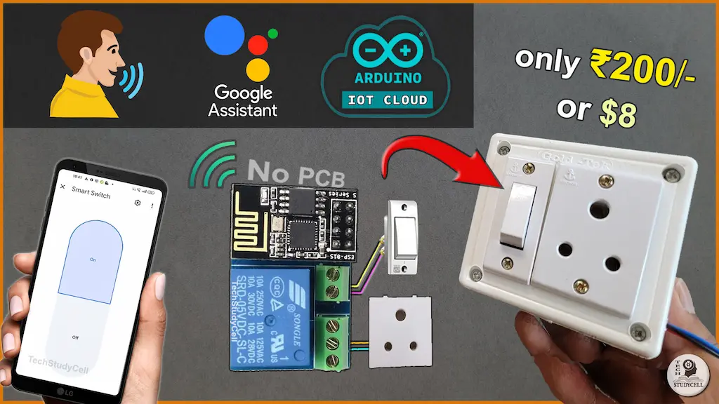
In this ESP8266 project, I demonstrate how to build a simple IoT project using the ESP01 Arduino Cloud. To get started, you’ll need an ESP-01/01s relay v4.0 and an ESP01. This setup allows you to control your devices through Arduino IoT Remote, Google Assistant, and manual switch.


I have used the FREE plan of the Arduino IoT cloud platform for this ESP01 ESP8266 home automation project. You can buy the “ESP-01/01s relay v4.0” from any online store.
So if you follow all the steps, you can easily make this IoT project with ESP-01 ESP8266 and Arduino IoT Cloud.
Table of Contents
Required Components:

Circuit of the ESP01 Relay IoT project

In the circuit, you can use any 5V DC power supply.
The switch is wired between the NO and COM terminals of the relay. Since the switch isn’t directly linked to the ESP01, real-time feedback monitoring isn’t possible.
The relay control pin is connected to the GPIO-0 of the ESP-01.
Instead of the socket, you can also connect a lamp with the relay as per the following circuit.

Please take proper safety precautions while connecting the AC appliances.
Tutorial video on ESP01 IoT Project
In the ESP01 tutorial video, I covered the following topics.
- Explained the circuit for Programming the ESP01 using FTDI232.
- How to configure the Arduino IoT Cloud for ESP8266.
- Circuit for connecting all the components with ESP01 relay.
- Add the device to the Google Home app.
Circuit for Programming ESP01
Please refer to this article for Programming ESP-01 using Arduino IDE.

Connect the GPIO-0 with GND and press the RESET button to enter programming mode.
Arduino IoT Cloud FREE account setup
For this IoT project, I have used the Arduino Cloud Free plan.

First, sign up for the Arduino IoT Cloud platform.
Then create a Thing and associate the ESP8266 device (Generic ESP8266 module) with the Thing. You can refer to the following Arduino IoT Cloud tutorial.
Getting Started with Arduino IoT
After creating the Thing, we have to add one cloud variable.

- Variable name: Smart_Switch
- Variable Type: Smart Plug
- Variable Permission: Read & Write
- Variable Update Policy: On change.
Then create the Dashboard with the Switch widget.


Here give the name Smart Switch and assign the Smart_Switch variable.
Program ESP8266 with Arduino IDE
In the tutorial video, I explained all the steps to program the ESP32 using Arduino IDE.
- Update the Preferences –> Aditional boards Manager URLs: https://dl.espressif.com/dl/package_esp32_index.json, http://arduino.esp8266.com/stable/package_esp8266com_index.json
- Then install the ESP8266 board from the Board Manager or Click Here to download the ESP8266 board.
- Download the required libraries from the following links:
- ArduinoIoTCloud version 1.0.2 by Arduino and all the dependencies.
Go to Sketch -> Include Libraries -> Manage Libraries in Arduino IDE.

When you try to install the ArduinoIoTCloud library, it will ask you to install all the dependencies. Then Click on Install All.
Code for ESP01 Arduino Cloud control relay
In the sketch, you have to update the following details.
const char DEVICE_LOGIN_NAME[]  = ""; //Enter DEVICE ID

const char SSID[]               = ""; //Enter WiFi SSID (name)
const char PASS[]               = "";  //Enter WiFi password
const char DEVICE_KEY[]         = "";  //Enter Secret device password (Secret Key)
After making these changes, please upload the code to ESP32.
Here’s a line-by-line explanation of the code:
1. Include Libraries
#include <ArduinoIoTCloud.h>
#include <Arduino_ConnectionHandler.h>
#include <ESP8266Wifi.h>
#include <ArduinoIoTCloud.h>: Includes the Arduino IoT Cloud library to interact with the Arduino IoT Cloud platform.#include <Arduino_ConnectionHandler.h>: Provides connection handling utilities for connecting to the Arduino IoT Cloud.#include <ESP8266Wifi.h>: Includes the ESP8266 Wi-Fi library to enable Wi-Fi connectivity on the ESP8266 module.
2. Define Device and Network Credentials
const char DEVICE_LOGIN_NAME[]  = ""; //Enter DEVICE ID
const char SSID[]               = "";    //Enter WiFi SSID (name)
const char PASS[]               = "";    //Enter WiFi password
const char DEVICE_KEY[]         = "";    //Enter Secret device password (Secret Key)
DEVICE_LOGIN_NAME: A unique identifier for your device on the Arduino IoT Cloud.SSID: The name of your Wi-Fi network.PASS: The password for your Wi-Fi network.DEVICE_KEY: A secret key for authenticating your device with the Arduino IoT Cloud.
3. Define GPIO Pin for Relay
#define RelayPin1 0 //D0
RelayPin1: Defines the GPIO pin (D0 on the ESP8266) connected to the relay module.
4. Declare Callback Function
void onSwitch1Change();
onSwitch1Change(): Declares a callback function that will be triggered when the state of the smart switch changes in the Arduino IoT Cloud.
5. Define Cloud Object
CloudSmartPlug smart_Switch; //change name (if required)
smart_Switch: Creates a cloud object of typeCloudSmartPlugto represent a smart plug in the Arduino IoT Cloud. This object can be controlled remotely.
6. Initialize Properties for Arduino IoT Cloud
void initProperties(){
  ArduinoCloud.setBoardId(DEVICE_LOGIN_NAME);
  ArduinoCloud.setSecretDeviceKey(DEVICE_KEY);
  ArduinoCloud.addProperty(smart_Switch, READWRITE, ON_CHANGE, onSwitch1Change); //change name (if required)
}
ArduinoCloud.setBoardId(): Sets the unique board ID for your device.ArduinoCloud.setSecretDeviceKey(): Sets the secret key for device authentication.ArduinoCloud.addProperty(): Adds thesmart_Switchproperty to the Arduino IoT Cloud, allowing it to be read and written. TheonSwitch1Changefunction is called whenever the property changes.
7. Set Up Wi-Fi Connection
WiFiConnectionHandler ArduinoIoTPreferredConnection(SSID, PASS);
WiFiConnectionHandler: Initializes a Wi-Fi connection handler with the provided SSID and password.
8. Setup Function
void setup() {
  Serial.begin(9600);
  delay(1500);
  initProperties();
  ArduinoCloud.begin(ArduinoIoTPreferredConnection);
  setDebugMessageLevel(2);
  ArduinoCloud.printDebugInfo();
  pinMode(RelayPin1, OUTPUT);
  digitalWrite(RelayPin1, HIGH);
}
Serial.begin(9600): Initializes serial communication at 9600 baud rate for debugging.delay(1500): Adds a delay to allow time for the Serial Monitor to open (if used).initProperties(): Calls the function to initialize properties for the Arduino IoT Cloud.ArduinoCloud.begin(): Connects to the Arduino IoT Cloud using the preferred Wi-Fi connection.setDebugMessageLevel(2): Sets the debug message level to display detailed information.ArduinoCloud.printDebugInfo(): Prints debug information to the Serial Monitor.pinMode(RelayPin1, OUTPUT): Configures the relay pin as an output.digitalWrite(RelayPin1, HIGH): Ensures the relay is turned off initially (assuming HIGH turns off the relay).
9. Loop Function
void loop() {
  ArduinoCloud.update();
}
ArduinoCloud.update(): Continuously updates the Arduino IoT Cloud connection and handles incoming/outgoing data.
10. Callback Function Implementation
void onSwitch1Change() {
  if (smart_Switch == 1) {
    digitalWrite(RelayPin1, LOW);
    Serial.println("Device1 ON");
  } else {
    digitalWrite(RelayPin1, HIGH);
    Serial.println("Device1 OFF");
  }
}
smart_Switch == 1: Checks if the smart switch is turned on (value is 1).digitalWrite(RelayPin1, LOW): Turns on the relay (assuming LOW activates the relay).digitalWrite(RelayPin1, HIGH): Turns off the relay.Serial.println(): Prints the relay state to the Serial Monitor for debugging.
Place the circuit inside a Switch Box

Now place the ESP01 relay inside the switch box. Please refer to the circuit.
Then connect the Google Home with Arduino Cloud.
PCB for the ESP01 project
Although you can buy the readymade PCB from an online store, but to add more features to this circuit, you can design your own PCB like the following.

You can order any custom-designed PCBs from PCBWay at very reasonable prices.

PCBWay not only produces FR-4 and Aluminum boards but also advanced PCBs like Rogers, HDI, and Flexible and Rigid-Flex boards, at very affordable prices.
For the online instant quote page please visit – pcbway.com/orderonline
You can also explore different PCB projects from their Open-source community pcbway.com/project/.
For more details please visit the
Control ESP01 Relay with Google Assistant

Now, you can also ask Google Assistant, to turn on the switch or control the appliance from the Google Home app.

You can also control the relay from the Arduino IoT Remote app.
Control the appliance with the Switch

If there is no internet, you can control the appliances with the manual switch.
Click Here for more such ESP8266 projects.
Please do share your feedback on this IoT project


