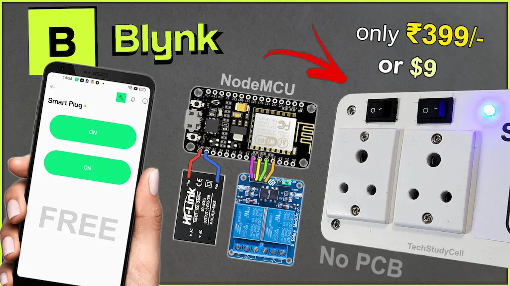
Smart home automation has become an essential part of modern living, and building your own DIY Smart Plug is a great way to learn IoT practically. In this project, we build a smart plug using ESP8266 NodeMCU and the Blynk IoT platform, allowing you to control home appliances from your mobile phone as well as from manual latched switches.

This project is designed to be reliable, offline-friendly, and optimized for the Blynk free plan. Even if WiFi is unavailable, manual control continues to work instantly, and when the internet is restored, the device automatically reconnects to Blynk.


Table of Contents
Project Features:
- Control appliances using Blynk IoT mobile app
- Manual control using latched (ON/OFF) switches
- Works even without WiFi
- Automatic reconnection to WiFi and Blynk
- EEPROM memory to restore relay states after power failure
- WiFi status LED indication
- Optimized code with minimal cloud requests
- Suitable for DIY Smart Plug and Home Automation projects
Required Components for DIY Smart Plug

- ESP8266 NodeMCU
- 2-Channel Relay Module (Active-LOW)
- 2 × Latched Switches (Toggle or Rocker)
- LED + 220Ω Resistor (WiFi indicator)
- AC socket (2 qty)
- 5V AC to DC converter
Circuit of the Smart Plug using NodeMCU

Pin Configuration
| Function | NodeMCU Pin | GPIO |
|---|---|---|
| Relay 1 | D5 | GPIO14 |
| Relay 2 | D6 | GPIO12 |
| Switch 1 | D1 | GPIO5 |
| Switch 2 | D2 | GPIO4 |
| WiFi LED | D0 | GPIO16 |
Note: Relays are active-LOW, meaning LOW = ON and HIGH = OFF.
The AC sockets are connected across the NO and COM terminals of the relays.
I have used a 5V 1Amp mobile charger to supply the circuit.
Please take proper safety precautions while working with High Voltage.
Tutorial video on Smart Plug using ESP8266 & Blynk
In the Internet of Things tutorial video, I have explained all the steps in detail for this ESP8266 smart plug.
How This Smart Plug Works
The ESP8266 NodeMCU continuously monitors the state of two latched switches. Each switch directly controls a relay, turning it ON when the switch pin is connected to GND. This provides a traditional wall-switch-like experience.
At the same time, the same relays can be controlled remotely using the Blynk IoT app through virtual pins V1 and V2. Whenever a relay state changes—either from the mobile app or from a physical switch—the new state is immediately applied to the relay, sent back to Blynk for real-time feedback (if connected), and saved to EEPROM if enabled.
On power-up, the NodeMCU reads the last saved relay states from EEPROM and restores them automatically. A timer periodically checks the WiFi and Blynk connection and updates the WiFi LED. To keep manual control responsive, Blynk.run() executes only when WiFi is available.
Set up Blynk IoT Cloud for the ESP8266 Project
You can refer to the following article to set up the new Blynk cloud account
Getting started with New Blynk 2.0 IoT platform
Create Blynk Template
While creating the template, I selected ESP8266 as hardware and connection type as WiFi.
Add two Datastreams:

- V1 → Relay 1 (Datatype: Integer, Min: 0, Max: 1)
- V2 → Relay 2 (Datatype: Integer, Min: 0, Max: 1)
Set up Web Dashboard

Add Switch widgets in the dashboard and connect the widgets with Datastreams.
Create a device from the template

Go to Devices –> New Device, select “From Template“.
Then select the Template name and enter a device name.

Copy Template ID, Template Name, and Auth Token
Program NodeMCU with Arduino IDE
For this IoT-based home automation project, I have used the Arduino IDE to program the ESP8266 NodeMCU.
First update the Preferences –> Aditional boards Manager URLs: https://dl.espressif.com/dl/package_esp32_index.json, http://arduino.esp8266.com/stable/package_esp8266com_index.json
Then install the ESP8266 board from the Board manager or Click Here to download the ESP8266 board.
Download the required libraries from the following links:
- Blynk Library (Version 1.3.2)

Source Codes for Blynk IoT Project with NodeMCU
Click on the following buttons to download the source code for this NodeMCU project.
In the code, update the Template ID, Template Name, and Auth Token.
#define BLYNK_TEMPLATE_ID "YOUR_TEMPLATE_ID"
#define BLYNK_TEMPLATE_NAME "YOUR_DEVICE_NAME"
#define BLYNK_AUTH_TOKEN "YOUR_AUTH_TOKEN"
Enter the WiFi credentials.
/ Your WiFi credentials
char ssid[] = "";
char pass[] = "";
This project uses EEPROM to remember relay states after power loss.
- If
EEPROM_FLAG = true→ relay states are saved and restored - If
EEPROM_FLAG = false→ relays always start OFF
const bool EEPROM_FLAG = true;This makes the project flexible for different use cases.
Explanation for every major code block
Below is a paragraph-by-paragraph explanation for every major code block, describing exactly what each section does and how it contributes to the project.
/* Fill-in your Template info (Blynk IoT) */
#define BLYNK_TEMPLATE_ID ""
#define BLYNK_TEMPLATE_NAME ""
#define BLYNK_AUTH_TOKEN ""
This first block is where you configure the Blynk IoT template information. BLYNK_TEMPLATE_ID and BLYNK_TEMPLATE_NAME identify your device template on the Blynk cloud, and BLYNK_AUTH_TOKEN is the unique token that links this specific NodeMCU device to your Blynk project. When you paste the actual values from the Blynk web dashboard or app, the library uses them to authenticate and register your device with the correct project on the server.
// Your WiFi credentials
char ssid[] = "";
char pass[] = "";
Here you define the Wi-Fi network credentials. ssid is the Wi-Fi name (SSID), and pass is the password for that network. The ESP8266 will use these strings when calling WiFi.begin() to connect to your router. If your network is open (no password), you would leave pass as an empty string.
#include <ESP8266WiFi.h>
#include <BlynkSimpleEsp8266.h>
#include <EEPROM.h>
These #include lines pull in the required libraries. ESP8266WiFi.h gives you all the functions to connect the ESP8266 to Wi-Fi. BlynkSimpleEsp8266.h is the Blynk library specifically adapted for the ESP8266, handling all communication with the Blynk cloud. EEPROM.h provides functions to read and write small amounts of data to the flash memory, which you use to remember relay states across resets or power loss.
// ============ Blynk Auth ============
char auth[] = BLYNK_AUTH_TOKEN;
This line copies the BLYNK_AUTH_TOKEN macro into a mutable char array called auth. The Blynk.config() function later expects a C-style string, so this auth variable is what you pass to it. It’s essentially the runtime version of your Blynk authentication token.
// ============ Pin Definitions ============
#define RELAY1_PIN   D5      // GPIO14
#define RELAY2_PIN   D6      // GPIO12

#define SWITCH1_PIN  D1      // GPIO5  (latched switch 1)
#define SWITCH2_PIN  D2      // GPIO4  (latched switch 2)

#define WIFI_LED_PIN 16      // D0 (WiFi status LED, ACTIVE-HIGH)
This section defines the hardware pins used in the project. RELAY1_PIN and RELAY2_PIN are connected to the inputs of the two relay modules, using NodeMCU pins D5 and D6 (internally GPIO14 and GPIO12). SWITCH1_PIN and SWITCH2_PIN are connected to latched switches on D1 and D2 (GPIO5 and GPIO4). Finally, WIFI_LED_PIN is set to GPIO16 (D0) and is used as the Wi-Fi/Blynk status LED; you’re using it in an “active-HIGH” configuration, meaning the LED turns ON when this pin is set HIGH.
// Active-LOW relay logic
#define RELAY_ON   LOW
#define RELAY_OFF  HIGH
These defines capture how your relay modules behave electrically. Your relays are “active-low,” which means they switch ON when the input pin is driven LOW and switch OFF when the pin is HIGH. By naming these as RELAY_ON and RELAY_OFF, you can write clearer code later (digitalWrite(RELAY1_PIN, RELAY_ON) instead of directly using LOW), and the intent is obvious.
// ============ Blynk Virtual Pins ============
#define VPIN_RELAY1   V1
#define VPIN_RELAY2   V2
Here you define which Blynk virtual pins control each relay. VPIN_RELAY1 is mapped to V1, and VPIN_RELAY2 to V2. In the Blynk dashboard, you’ll set up button widgets linked to V1 and V2. When you press those buttons in the app, Blynk sends values to these virtual pins, and your BLYNK_WRITE handlers will respond to them and control the relays.
// ============ EEPROM Settings ============
// EEPROM addresses
#define EEPROM_RELAY1_ADDR   1
#define EEPROM_RELAY2_ADDR   2
This part sets up the addresses in EEPROM memory where you will store the state of each relay. EEPROM_RELAY1_ADDR and EEPROM_RELAY2_ADDR are the byte positions in the EEPROM where you’ll write and read the ON/OFF states. Each is just a single byte (0 or 1). Starting from 1 and 2 leaves EEPROM address 0 free if you want a version flag or other meta data later.
// EEPROM flag:
// true  -> use EEPROM (read + write)
// false -> ignore EEPROM (no read, no write, relays start OFF)
const bool EEPROM_FLAG = true;
This boolean flag controls whether EEPROM memory is actually used. When EEPROM_FLAG is true, the code reads the last saved relay states on startup and writes any changes to EEPROM. If you set it to false, the code completely ignores EEPROM—relays always start OFF at boot, and no flash writes are performed. This is handy if you want to temporarily disable memory saving without changing all the EEPROM-related functions.
// ============ Global Variables ============
bool relay1State = false;   // false = OFF, true = ON
bool relay2State = false;

bool lastSwitch1State = HIGH;  // for change detection
bool lastSwitch2State = HIGH;

int wifiFlag = 0;

BlynkTimer timer;
These are your global variables that hold runtime state. relay1State and relay2State track whether each relay should be ON (true) or OFF (false) in your software logic. lastSwitch1State and lastSwitch2State are used to detect changes in the latched switch positions by comparing the current reading with the previous one. wifiFlag is an integer used as a simple status indicator (0/1) for connection state; it’s mostly for debugging or future expansion. timer is a BlynkTimer object, which you use to schedule periodic tasks like checking Wi-Fi/Blynk status without blocking the main loop.
// ============ Helper: EEPROM ============

void saveRelayStatesToEEPROM() {
  if (!EEPROM_FLAG) {
    Serial.println(F("[EEPROM] FLAG disabled, not saving states"));
    return;
  }

  Serial.print(F("[EEPROM] Saving Relay1="));
  Serial.print(relay1State);
  Serial.print(F(" Relay2="));
  Serial.println(relay2State);

  EEPROM.write(EEPROM_RELAY1_ADDR, relay1State ? 1 : 0);
  EEPROM.write(EEPROM_RELAY2_ADDR, relay2State ? 1 : 0);
  EEPROM.commit();
}
This function writes the current relay states into EEPROM so they can be restored after a reset. First, it checks EEPROM_FLAG; if the flag is false, it prints a message and returns immediately, effectively disabling EEPROM writes. If enabled, it prints the states to the Serial Monitor for debugging. Then it writes 1 or 0 to the designated addresses depending on whether each relay is ON or OFF, and finally calls EEPROM.commit() to actually store the changes in flash memory. Without commit(), the changes would stay only in a RAM buffer and be lost on reset.
void loadRelayStatesFromEEPROM() {
  if (!EEPROM_FLAG) {
    Serial.println(F("[EEPROM] FLAG disabled, not loading states. Starting with both OFF."));
    relay1State = false;
    relay2State = false;
    return;
  }

  uint8_t r1 = EEPROM.read(EEPROM_RELAY1_ADDR);
  uint8_t r2 = EEPROM.read(EEPROM_RELAY2_ADDR);

  relay1State = (r1 == 1);
  relay2State = (r2 == 1);

  Serial.print(F("[EEPROM] Loaded Relay1="));
  Serial.print(relay1State);
  Serial.print(F(" Relay2="));
  Serial.println(relay2State);
}
This function restores relay states from EEPROM at startup. If EEPROM_FLAG is false, it logs a message, forces both relay1State and relay2State to false (OFF), and exits. When EEPROM is enabled, it reads one byte from each relay’s EEPROM address into r1 and r2. If the value is 1, the corresponding relay state becomes true; if not, it defaults to false. After updating the state variables, it prints the loaded states to the Serial Monitor. This allows your relays to come back in the same ON/OFF configuration they had before power loss (when the flag is enabled).
// ============ Helper: Relay Control ============

void applyRelayStates() {
  digitalWrite(RELAY1_PIN, relay1State ? RELAY_ON : RELAY_OFF);
  digitalWrite(RELAY2_PIN, relay2State ? RELAY_ON : RELAY_OFF);

  Serial.print(F("[RELAY] Apply states -> R1="));
  Serial.print(relay1State);
  Serial.print(F(" R2="));
  Serial.println(relay2State);
}
applyRelayStates() takes the logical ON/OFF states stored in relay1State and relay2State and actually drives the relay pins accordingly. Because your relays are active-low, it writes LOW to the pin when the relay state is true and HIGH when the state is false. The ternary operator (condition ? valueIfTrue : valueIfFalse) makes that mapping compact. It also logs the applied states to the Serial Monitor, which is useful to confirm the relays are matching the internal logic.
void setRelay1(bool on, const char* source) {
  relay1State = on;
  digitalWrite(RELAY1_PIN, on ? RELAY_ON : RELAY_OFF);

  Serial.print(F("[RELAY] Relay1 set to "));
  Serial.print(on ? F("ON") : F("OFF"));
  Serial.print(F(" from "));
  Serial.println(source);

  if (Blynk.connected()) {
    Blynk.virtualWrite(VPIN_RELAY1, relay1State);
  }

  saveRelayStatesToEEPROM();
}
setRelay1() is a helper function to change Relay 1 in a consistent way. It takes a boolean on (desired state) and a string source describing who triggered the change (e.g., "Blynk" or "Switch1"). It updates relay1State, drives the relay pin with the correct level (LOW for ON, HIGH for OFF), and prints a debug message mentioning both the new state and the source. If the device is currently connected to Blynk, it sends the new state back to the app using Blynk.virtualWrite(VPIN_RELAY1, relay1State), keeping the app button in sync. Finally, it calls saveRelayStatesToEEPROM() to remember this new state across resets.
void setRelay2(bool on, const char* source) {
  relay2State = on;
  digitalWrite(RELAY2_PIN, on ? RELAY_ON : RELAY_OFF);

  Serial.print(F("[RELAY] Relay2 set to "));
  Serial.print(on ? F("ON") : F("OFF"));
  Serial.print(F(" from "));
  Serial.println(source);

  if (Blynk.connected()) {
    Blynk.virtualWrite(VPIN_RELAY2, relay2State);
  }

  saveRelayStatesToEEPROM();
}
This function is the same idea, but for Relay 2. It sets relay2State, writes the proper active-low level to RELAY2_PIN, and prints which source caused the change. If Blynk is connected, it updates the virtual pin V2 so that the app reflects the new state. Then it saves to EEPROM if that feature is enabled. Using these dedicated setter functions keeps all logic—hardware driving, Blynk sync, and EEPROM saving—centralized in one place per relay.
// ============ WiFi / Blynk Status (no cloud writes) ============

void checkBlynkStatus() { // called every 10 seconds by timer
  bool wifiConnected  = (WiFi.status() == WL_CONNECTED);
  bool blynkConnected = Blynk.connected();

  if (!wifiConnected) {
    wifiFlag = 1;
    Serial.println(F("[WiFi] Not Connected"));
    digitalWrite(WIFI_LED_PIN, LOW);   // ACTIVE-HIGH -> OFF
    return;
  }

  // WiFi is OK
  if (!blynkConnected) {
    wifiFlag = 1;
    Serial.println(F("[Blynk] Not Connected, WiFi OK"));
    digitalWrite(WIFI_LED_PIN, LOW);   // OFF
  } else {
    wifiFlag = 0;
    digitalWrite(WIFI_LED_PIN, HIGH);  // ACTIVE-HIGH -> ON
    Serial.println(F("[Blynk] Connected"));
  }
}
This function is periodically called by BlynkTimer to monitor connection status and update the Wi-Fi LED. It first checks if the ESP8266 is connected to Wi-Fi using WiFi.status(). If not, it sets wifiFlag to 1, prints a message, turns the Wi-Fi LED OFF (LOW in an active-HIGH setup), and returns early. If Wi-Fi is connected, it then checks whether the Blynk client is connected to the cloud using Blynk.connected(). If Blynk is not connected, it logs that Blynk is down while Wi-Fi is OK and keeps the LED OFF. If both Wi-Fi and Blynk are connected, it sets wifiFlag back to 0, turns the LED ON (HIGH), and prints a “Connected” message. Importantly, this function does not send any data to Blynk, so it doesn’t consume your free plan request quota.
// ============ Blynk Events ============

// Blynk just connected to the cloud
BLYNK_CONNECTED() {
  Serial.println(F("[Blynk] BLYNK_CONNECTED()"));
  // Send current local relay states to app ONCE per connection
  Serial.println(F("[Blynk] Sending current relay states to server"));
  Blynk.virtualWrite(VPIN_RELAY1, relay1State);
  Blynk.virtualWrite(VPIN_RELAY2, relay2State);
}
BLYNK_CONNECTED() is a special callback that runs automatically whenever the device successfully connects (or reconnects) to the Blynk server. Inside this handler, you print a debug message and then send the current local relay states to the app using Blynk.virtualWrite() for both V1 and V2. This ensures that after any reconnection, the app buttons immediately show the actual relay states. This sync is done only once per connection, so it’s efficient and won’t repeatedly consume your request limit.
// App button V1
BLYNK_WRITE(VPIN_RELAY1) {
  int value = param.asInt();   // 0 or 1
  bool newState = (value == 1);

  Serial.print(F("[Blynk] V1 received: "));
  Serial.println(newState);

  setRelay1(newState, "Blynk");
}
This is the handler that responds when the Blynk app writes to virtual pin V1. When you tap the Relay1 button widget in the app, Blynk sends a value (usually 0 or 1) to V1, and this function runs. It reads that value into value, converts it to a boolean newState, and logs the received state. Then it calls setRelay1(newState, "Blynk") to actually change the relay, keep internal state consistent, update EEPROM, and send feedback if needed. This cleanly decouples the app input from the relay logic.
// App button V2
BLYNK_WRITE(VPIN_RELAY2) {
  int value = param.asInt();   // 0 or 1
  bool newState = (value == 1);

  Serial.print(F("[Blynk] V2 received: "));
  Serial.println(newState);

  setRelay2(newState, "Blynk");
}
Similarly, this handler is triggered whenever V2 receives a new value from the app. It reads the integer, converts it to a boolean newState, prints a message with the new state, and then calls setRelay2(newState, "Blynk"). This keeps the relay logic uniform, ensuring that Blynk control goes through the same path as manual switch control, including EEPROM saving and app feedback.
// ============ Latched Switch Handling ============
// Latched switch logic:
//   Switch to GND (LOW)  -> Relay ON
//   Switch open (HIGH)   -> Relay OFF

void handleSwitches() {
  bool currentSwitch1 = digitalRead(SWITCH1_PIN);
  bool currentSwitch2 = digitalRead(SWITCH2_PIN);

  // ---- Switch 1 ----
  if (currentSwitch1 != lastSwitch1State) {
    delay(10); // small debounce
    currentSwitch1 = digitalRead(SWITCH1_PIN);
    if (currentSwitch1 != lastSwitch1State) {
      lastSwitch1State = currentSwitch1;

      bool newRelay1State = (currentSwitch1 == LOW); // LOW = ON
      Serial.print(F("[SWITCH] Switch1 changed, pin="));
      Serial.print(currentSwitch1);
      Serial.print(F(" -> Relay1="));
      Serial.println(newRelay1State);

      setRelay1(newRelay1State, "Switch1");
    }
  }

  // ---- Switch 2 ----
  if (currentSwitch2 != lastSwitch2State) {
    delay(10); // small debounce
    currentSwitch2 = digitalRead(SWITCH2_PIN);
    if (currentSwitch2 != lastSwitch2State) {
      lastSwitch2State = currentSwitch2;

      bool newRelay2State = (currentSwitch2 == LOW); // LOW = ON
      Serial.print(F("[SWITCH] Switch2 changed, pin="));
      Serial.print(currentSwitch2);
      Serial.print(F(" -> Relay2="));
      Serial.println(newRelay2State);

      setRelay2(newRelay2State, "Switch2");
    }
  }
}
handleSwitches() continuously monitors the two latched switches and reacts when their positions change. It first reads the current logic levels from SWITCH1_PIN and SWITCH2_PIN. For each switch, it compares the current reading with the last stored state. If they differ, it does a short 10 ms delay for debouncing, reads again to confirm the change, and then updates lastSwitchXState. Because the switches are wired with INPUT_PULLUP and connected to GND when ON, a LOW reading means “switch ON” and HIGH means “switch OFF”. It calculates the new relay state (true if LOW, false if HIGH), logs the change, and calls the appropriate setRelayX() with "Switch1" or "Switch2" as the source. This way, manual changes immediately update the relay, the app, and EEPROM, even if Wi-Fi or Blynk are offline.
// ============ Setup ============

void setup() {
  Serial.begin(9600);
  delay(100);
  Serial.println();
  Serial.println(F("===== ESP8266 2-Relay Blynk + Latched Switch + EEPROM ====="));

  // EEPROM init
  EEPROM.begin(512);
  Serial.println(F("[EEPROM] Initialized"));

  // Pin modes
  pinMode(RELAY1_PIN, OUTPUT);
  pinMode(RELAY2_PIN, OUTPUT);
  pinMode(SWITCH1_PIN, INPUT_PULLUP);   // latched switch to GND
  pinMode(SWITCH2_PIN, INPUT_PULLUP);   // latched switch to GND
  pinMode(WIFI_LED_PIN, OUTPUT);

  // Default: all relays OFF
  relay1State = false;
  relay2State = false;
  applyRelayStates();

  // Load last states from EEPROM (if enabled)
  loadRelayStatesFromEEPROM();
  applyRelayStates();

  // Read initial switch states (for debug)
  lastSwitch1State = digitalRead(SWITCH1_PIN);
  lastSwitch2State = digitalRead(SWITCH2_PIN);
  Serial.print(F("[SWITCH] Initial Switch1="));
  Serial.println(lastSwitch1State);
  Serial.print(F("[SWITCH] Initial Switch2="));
  Serial.println(lastSwitch2State);

  // WiFi + Blynk setup
  digitalWrite(WIFI_LED_PIN, LOW); // ACTIVE-HIGH -> OFF initially
  Serial.println(F("[WiFi] Connecting..."));
  WiFi.begin(ssid, pass);

  Blynk.config(auth);
  delay(1000);

  // Timer to check connection status every 5 seconds
  timer.setInterval(5000L, checkBlynkStatus);

  Serial.println(F("[SETUP] Completed"));
}
The setup() function runs once at boot and initializes everything. It starts by opening the Serial port at 9600 baud for debugging and prints a header line. Then it initializes EEPROM with EEPROM.begin(512), reserving 512 bytes for use. Next, it sets the relay pins as outputs, the switch pins as INPUT_PULLUP (so they read HIGH by default and LOW when connected to GND through the latched switch), and the Wi-Fi LED pin as output. It initializes both relays as OFF in software and applies that state to the hardware. After that, it calls loadRelayStatesFromEEPROM() to restore the last saved relay states (if EEPROM is enabled) and applies those states again so the relays start with the remembered configuration. It reads and prints the initial switch readings, which helps you verify the wiring. For network setup, it turns OFF the Wi-Fi LED initially, starts connecting to the router with WiFi.begin(ssid, pass), and configures the Blynk client with Blynk.config(auth) (non-blocking). A short delay gives the Wi-Fi stack time to start. Then, it sets up a timer to call checkBlynkStatus() every 5 seconds to update LED and logs. Finally, it prints that setup is complete.
// ============ Loop ============

void loop() {
  // Manual switches always work (even if WiFi/Blynk are down)
  handleSwitches();

  // Only run Blynk when WiFi is connected to avoid blocking in no-WiFi mode
  if (WiFi.status() == WL_CONNECTED) {
    Blynk.run();
  }

  timer.run();
}
The loop() function runs continuously and keeps the device responsive. First, it calls handleSwitches() on every iteration so physical switch changes are detected immediately, whether or not there is internet or Blynk connection. Then, it checks if Wi-Fi is connected. Only when WiFi.status() reports a connection does it call Blynk.run(), which processes Blynk communication and keeps the connection alive. This avoids long blocking timeouts when there is no Wi-Fi, so manual control stays snappy. Finally, timer.run() is called to execute any scheduled timer callbacks (like checkBlynkStatus()) at the right intervals without using delay-based blocking code.
You can also design a PCB to make the circuit compact and order it from PCBWay
PCBWay – Professional PCB Assembly Services
PCBWay offers fast, high-quality PCB assembly with lead times starting from 24 hours. Choose from Turn-key, Partial Turn-key, or Consigned options to match your project requirements.

Now you can save up to 50% OFF in their Christmas Big Sales (Click Here)

- Log in to your PCBWay account
- Go to Personal Center → My Coupons
- Enter your promo code
- Click Check to verify the code
- Click Apply to your balance
- Coupon is added and ready to use
Make the Smart Plug

Here I will place the complete circuit inside a switch box. So first, cut the group for the switch, socket, and LED.

Now connect all the components as per the circuit.
Safety Notes
- Always use proper AC-rated relay modules
- Ensure good isolation between AC and low-voltage circuits
- Use a plastic enclosure for the smart plug
- Never touch live AC wires while testing
Set up the Blynk IoT App for Smart Plug

- Install the new Blynk IoT app from the Google Play Store or App Store. Then log in to the Blynk IoT Platform.
- Tap on the Device name.
- Now tap on the settings icon (on the right) to add widgets.
- Tap on “+” icon and add 2 Button widgets from the Widget Box.
- Then tap on the widget to go to the settings.
- In the settings, enter the name, select the Datastream, Mode will be Switch. Then exit from the widget.
- After setting all the widgets, tap on the exit button at the top.
Conclusion
This ESP8266 NodeMCU Blynk IoT project demonstrates how to build a reliable DIY Smart Plug with both manual and mobile control. With features like EEPROM memory, offline operation, and optimized cloud usage, it is ideal for beginners and advanced makers alike.
If you are looking for a practical IoT project with real-world usability, this smart plug is a perfect starting point.


