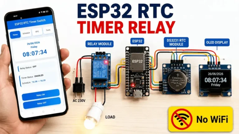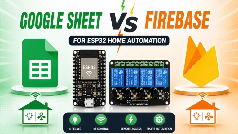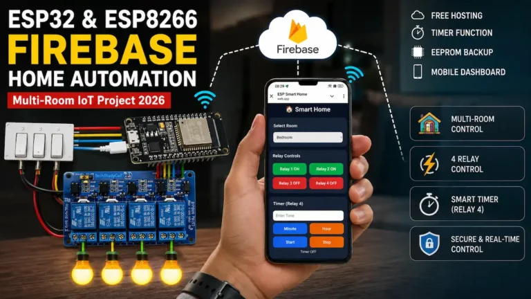
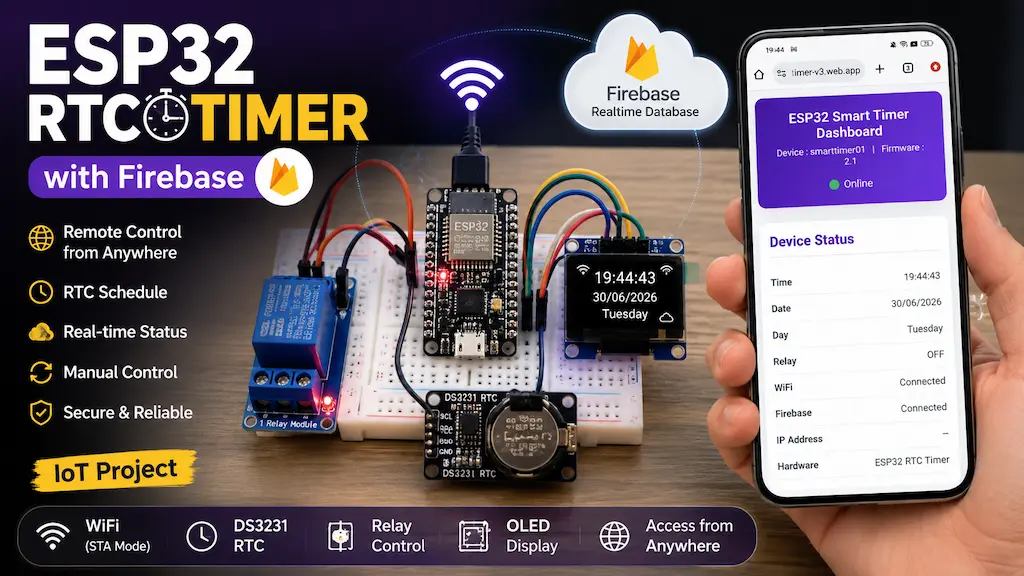

Want to control a timer relay from anywhere in the world? In this DIY IoT project, we will build a cloud-based ESP32 RTC Timer using the DS3231 Real-Time Clock module and Firebase Realtime Database.
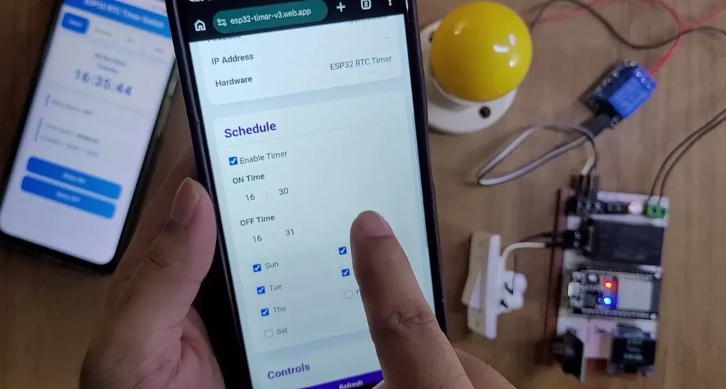
Unlike a traditional RTC timer that can only be configured locally, this project combines an ESP32 microcontroller, a precision RTC module, and a cloud-connected web dashboard. You can monitor the device status, control the relay, configure timer schedules, synchronize the RTC, and restart the ESP32 remotely using a mobile phone, tablet, or computer.
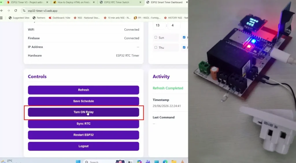
The ESP32 connects to your existing WiFi router in Station (STA) mode and communicates with Firebase over the internet. The web dashboard also connects to Firebase, allowing you to control your device without being connected to the same local WiFi network.
The best part? The ESP32 automatically creates the required database structure when it connects to Firebase for the first time, so you do not need to manually import a JSON database file.
Let’s explore the features, hardware requirements, circuit connections, Firebase configuration, and working principle of this ESP32 Firebase Smart Timer project.
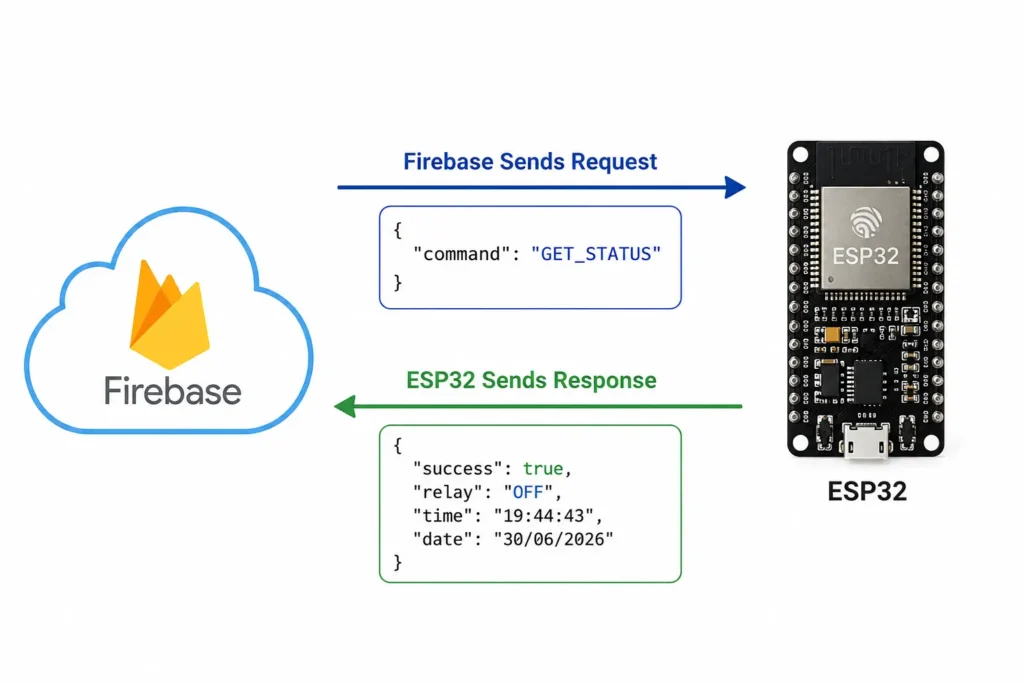
Table of Contents
Project Overview
This project is designed for anyone interested in ESP32 IoT projects, RTC-based automation, cloud-connected relay control, and custom web dashboards.
The DS3231 RTC module maintains the date and time, while the ESP32 processes the timer schedule and controls the relay. Firebase provides the cloud communication layer between the ESP32 and the web dashboard.
Tutorial video on ESP32 RTC Firebase Project
Key Features
- Cloud-based remote control: Control the relay through the web dashboard from anywhere with internet access.
- DS3231 RTC timer: Maintain accurate time for scheduled relay operation.
- Firebase Realtime Database: Exchange commands, status information, schedules, and responses.
- Secure dashboard login: Authenticate dashboard users using Firebase Email/Password Authentication.
- Responsive web dashboard: Access the interface from a smartphone, tablet, or desktop browser.
- Remote relay control: Turn the relay ON or OFF from the dashboard.
- Timer schedule management: Enable the timer, configure ON/OFF times, and select operating days.
- RTC synchronization: Update the DS3231 date and time from the dashboard.
- Remote ESP32 restart: Restart the device without physically accessing it.
- Manual switch control: Operate the relay locally using a push button or manual switch.
- OLED display: View the current time, date, day, and other device information locally.
- WiFi and Firebase status LED: Indicate the device’s connection and initialization status.
- Automatic database structure creation: Create the required Firebase nodes when they are missing.
- Device status monitoring: Display the relay state, RTC time, date, WiFi status, and cloud connection status.
- Command timeout handling: Detect commands that do not receive a timely response and show a failure state on the dashboard.
Required Component for the ESP32 RTC project
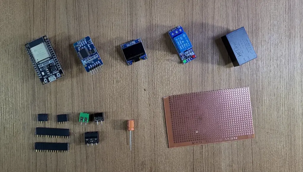
- ESP32 Devkit V1.
- DS3231 RTC module
- 1-channel 5V SPDT Relay Module.
- 25uF DC capacitor (optional)
- AC-DC converter (5V) HLK-5m05 (optional)
- 0.96-inch I2C OLED Display (optional)
Circuit of the ESP32 DS3231 RTC Timer Relay
Now it’s time to assemble the hardware. Connect the ESP32, DS3231 RTC module, Relay Module, OLED Display, and Manual Switch according to the circuit diagram below.
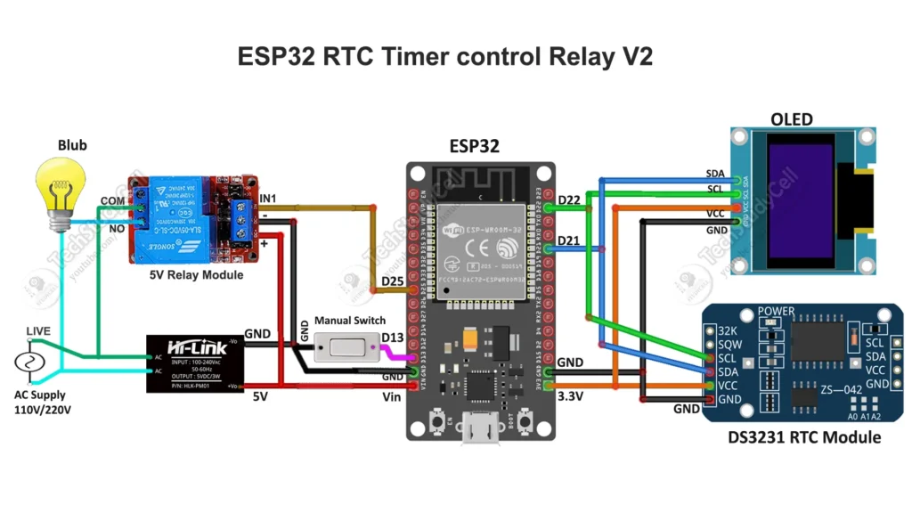
I have used D25 GPIO to control the relay module.
The DS3231 module and OLED (optional) are connected with D22 & D21 GPIO.
For manual control, you can also connect a latched switch across the D13 and GND.
You can also connect a push-button across the D13 and GND as per the following circuit.
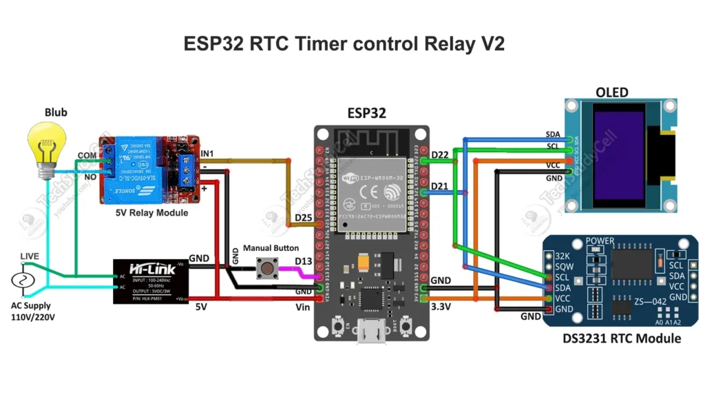
You can also use a 5V 5Amp mobile charger to supply the circuit instead of AC to DC converter.
Please take proper safety precautions while connecting the AC appliances.
How Does the ESP32 Firebase Smart Timer Work?
The project has three main parts: the ESP32 controller, Firebase Realtime Database, and the web dashboard.
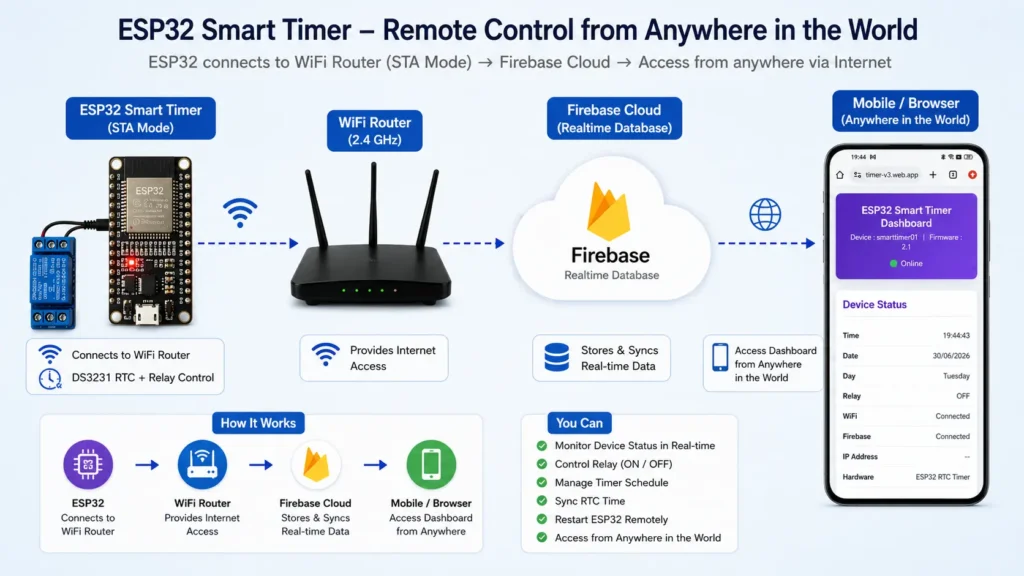
1. ESP32 Controller
The ESP32 is the main processing unit. It connects to the local WiFi router, authenticates with Firebase, reads incoming commands, processes the timer schedule, and controls the relay.
The ESP32 also communicates with the DS3231 RTC module over I2C and updates the OLED display.
2. Firebase Realtime Database
Firebase acts as the communication bridge between the ESP32 and the web dashboard.
It stores the device information, current status, timer schedule, pending commands, and command responses. The ESP32 checks for commands, executes the requested operation, uploads the result, and clears the processed command.
3. Web Dashboard
The dashboard is built using HTML, CSS, and JavaScript. Firebase Authentication handles the login process, while the Firebase JavaScript SDK communicates with the Realtime Database.
After login, users can monitor the device, operate the relay, save schedules, synchronize the RTC, refresh device information, and restart the ESP32 remotely.
Communication Flow
- The user clicks a control on the web dashboard.
- The dashboard writes the requested command or data to Firebase.
- The ESP32 reads the command from the appropriate database path.
- The ESP32 executes the requested operation.
- The ESP32 updates the status and response nodes in Firebase.
- The dashboard receives the updated data and displays the result.
This request-and-response architecture keeps the dashboard and the ESP32 synchronized through the cloud.
Understanding STA Mode
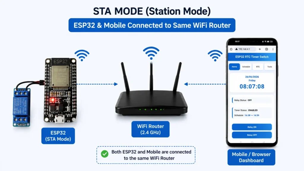
This version of the project uses WiFi Station (STA) mode.
In STA mode, the ESP32 connects to an existing WiFi router instead of creating its own WiFi hotspot. The router provides internet connectivity, allowing the ESP32 to communicate with Firebase.
The mobile phone or computer running the dashboard can use any internet connection. It does not have to be connected to the same router as the ESP32.
For example, you can leave the ESP32 connected to your home WiFi and operate the timer dashboard from your office or while travelling.
Important: If WiFi or internet access becomes unavailable, dashboard commands cannot reach the ESP32. The local RTC-based scheduling and manual controls can continue to work as long as the ESP32 and its hardware remain powered and the firmware is functioning correctly.
Firebase Setup
Before uploading the firmware, create and configure a Firebase project.
Step 1: Create a Firebase Project
- Open the Firebase Console: https://console.firebase.google.com/
- Create a new project or select an existing project.
- Give your project a suitable name.
- Complete the project creation process.
Step 2: Enable Email/Password Authentication
- Open Authentication in the Firebase Console.
- Go to the sign-in method settings.
- Enable Email/Password authentication.
- Create the user account that will be used to log in to the dashboard.
The dashboard uses these credentials to authenticate users. Do not hardcode a user’s login email and password into the dashboard JavaScript.
Step 3: Create a Realtime Database
- Open Realtime Database in the Firebase Console.
- Create a database.
- Select the appropriate database location.
- Copy the database URL for the Arduino configuration.
Configure Firebase Realtime Database security rules so that authenticated users can access only the data they are authorized to read and modify. Do not leave unrestricted public read/write access enabled in a production deployment.
Step 4: Register a Web App
- Open Project Settings.
- Register a web application.
- Copy the Firebase web configuration.
- Add the configuration to the dashboard’s
script.jsfile.
The web configuration typically includes the API key, authentication domain, project ID, and Realtime Database URL.
The Firebase web configuration identifies your project; it does not replace authentication or database security rules.
Configure the Arduino Sketch
Open the ESP32 firmware in Arduino IDE and update the user configuration section.
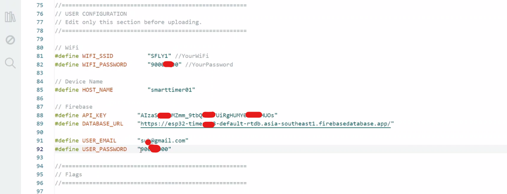
You will need to provide:
- WiFi SSID and password.
- Firebase API key.
- Firebase Realtime Database URL.
- Firebase authentication credentials used by the ESP32 firmware.
- Device name.
For example:
#define HOST_NAME "smarttimer01"Use the actual configuration macro names already present in your sketch.
Keep the Device Name Consistent
The device name in the Arduino sketch must match the device name configured in script.js.
Arduino sketch:
#define HOST_NAME "smarttimer01"Dashboard JavaScript:
let deviceName = "smarttimer01";Both must refer to the same database path. If the names differ, the ESP32 may write to one device node while the dashboard reads another, making the device appear offline.
For a new device, use a unique name and update it in both places.
Automatic Firebase Database Structure
One of the useful features of this project is that the ESP32 creates the required database nodes automatically when they are missing.
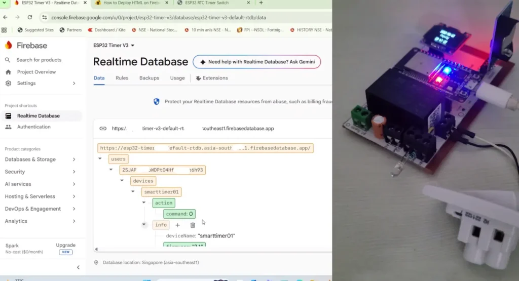
After successful Firebase authentication, the ESP32 obtains the authenticated user’s UID and builds the device path using that UID and the configured device name.
The resulting structure follows this pattern:
users
└── USER_UID
    └── devices
        └── smarttimer01
            ├── info
            ├── status
            ├── schedule
            ├── action
            └── response
Each node has a specific purpose.
Info Node
Stores device information, such as the device name, firmware version, hardware description, and online flag.
Status Node
Stores the latest reported device state, including the RTC time, date, day, relay state, WiFi status, and cloud status.
Schedule Node
Stores the timer configuration, including whether the timer is enabled, the ON and OFF times, and the selected days of operation.
Action Node
Stores the command that the ESP32 needs to process. For example, the dashboard can request a refresh, relay operation, schedule save, RTC synchronization, or remote restart.
Response Node
Stores the result of the latest command, including whether it succeeded, a descriptive message, and a timestamp.
The exact fields depend on the firmware implementation.
Because the ESP32 creates missing nodes automatically, you do not need to manually import a JSON file. Firebase Authentication, Realtime Database, and suitable security rules must still be configured correctly.
Set Up the Web Dashboard
The dashboard consists of three main files:
Web_Dashboard/
├── index.html
├── style.css
└── script.js
index.html
The HTML file defines the dashboard layout, login screen, device status section, timer schedule controls, action buttons, and response area.
style.css
The CSS file controls the appearance of the dashboard, including the two-column layout, responsive mobile view, colors, cards, buttons, and online/offline indicators.
script.js
The JavaScript file initializes the Firebase web app, handles user login and logout, reads and writes Realtime Database data, and processes dashboard actions.
Make sure the HTML file references the other files correctly:
<link rel="stylesheet" href="style.css">and:
<script type="module" src="script.js"></script>The JavaScript file uses ES modules to import the Firebase SDK.
Test the Dashboard Locally
You can use Visual Studio Code with the Live Server extension to serve the dashboard during development.
Open the dashboard through the local server rather than relying on a file:// URL. Check that login works, device information appears, and the dashboard can read the correct Firebase device node.
Deploy the Dashboard Using Firebase Hosting
Firebase Hosting allows you to make the web dashboard available through a public HTTPS URL.
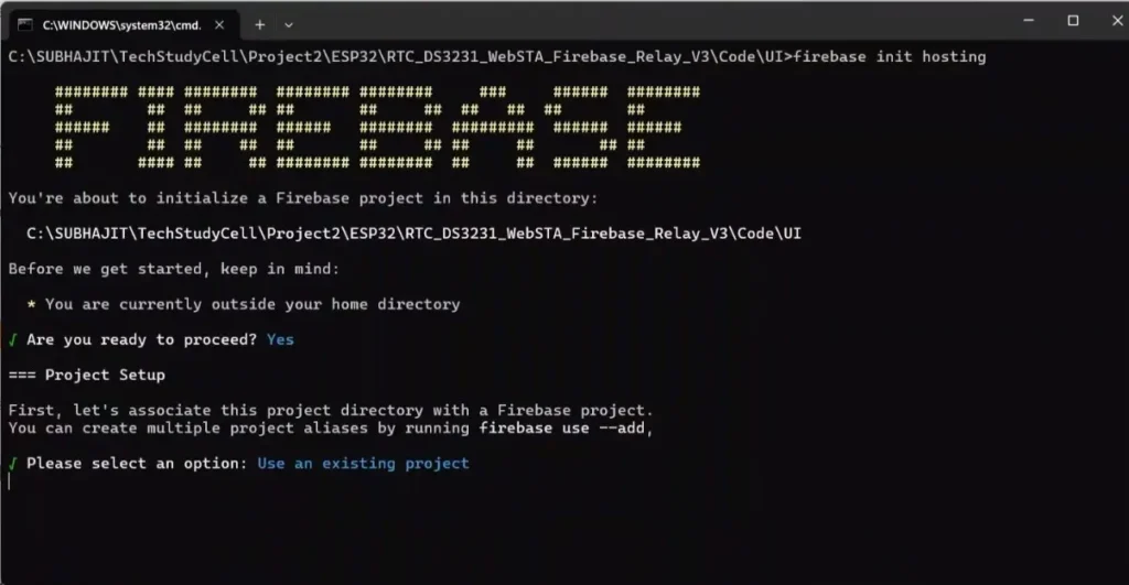
Your hosting folder should contain the three dashboard files, along with the Firebase Hosting configuration files:
firebase-hosting/
├── index.html
├── style.css
├── script.js
├── firebase.json
└── .firebaserc
After configuring Firebase Hosting with the Firebase CLI, deploy the dashboard using:
firebase deploy --only hostingFirebase Hosting will serve the HTML, CSS, and JavaScript files together. You do not need to deploy them individually.
Once deployment is complete, open the Hosting URL on a smartphone or computer, sign in, and verify that the dashboard is connected to the intended Firebase project.
Timer Scheduling and Relay Control
The timer schedule allows the relay to operate according to the configured time and days.
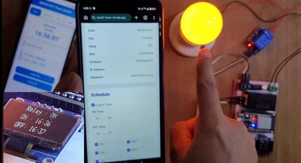
Save Schedule
The user selects the timer enable state, ON time, OFF time, and days of operation. When the Save Schedule button is pressed, the dashboard writes the schedule to Firebase. The ESP32 processes the save command and reports the result.
Relay ON and Relay OFF
The dashboard writes the appropriate relay command to the action node. The ESP32 reads the command, switches the relay, uploads its latest status, and sends a response to Firebase.
Refresh
The Refresh command asks the ESP32 to update its status and schedule information in Firebase so the dashboard can display the latest reported values.
RTC Synchronization
The RTC Sync function sends the requested date and time to Firebase. The ESP32 reads the RTC data, updates the DS3231 using the RTC library, uploads the new status, and returns a response.
Remote Restart
The Restart command allows the ESP32 to reboot remotely. The firmware should report the restart request and clear the pending command before restarting, so the same request is not unintentionally executed again.
Command Timeout and Offline Detection
A cloud-connected device may be unavailable because of a WiFi failure, loss of internet access, Firebase authentication problems, or a powered-off ESP32.
To improve the dashboard experience, the project uses command timeout handling. If the ESP32 does not return a response within the configured timeout, the dashboard can stop waiting, re-enable the controls, and display a failure message.
The dashboard should also distinguish between a successful Firebase write and successful execution by the ESP32. Writing a command to Firebase does not guarantee that the device received or completed it.
The online indicator should be based on a reliable device-status or heartbeat strategy. A previously stored online: true value alone cannot guarantee that a device is currently reachable after an unexpected disconnection.
Testing the Complete Project
Follow this checklist after configuring the Firebase project and uploading the firmware.
- Power the ESP32 and verify that it connects to the WiFi router.
- Check the serial monitor for successful Firebase authentication.
- Confirm that the ESP32 creates the required database nodes.
- Open the hosted web dashboard and sign in.
- Verify that the device name and status information appear.
- Test the Relay ON and Relay OFF buttons.
- Save a timer schedule and confirm that it is stored in Firebase.
- Test the Refresh command.
- Synchronize the RTC from the dashboard.
- Test the remote restart function.
- Disconnect the ESP32 from WiFi and verify the dashboard timeout and offline indication.
- Restore the WiFi connection and verify that the ESP32 reconnects and resumes cloud communication.
For the first test, use a low-voltage load or an LED-based relay test setup. Verify the relay’s electrical ratings and isolation before connecting any mains-powered appliance.
Troubleshooting
ESP32 Does Not Connect to Firebase
Check the WiFi credentials, internet connectivity, API key, database URL, authentication credentials, and Firebase Authentication settings. Also verify that the ESP32 obtains a valid authenticated UID.
Firebase Reports path not exist
Check that the ESP32 successfully created the expected database structure and that the device name matches the dashboard configuration. Confirm that the command path exists under the correct authenticated user’s UID.
Dashboard Shows the Device as Offline
Verify that the dashboard is reading the correct device node. Check the ESP32 serial monitor for Firebase connection errors and confirm that the status data is being uploaded. A stale online flag should not be treated as proof of a current connection.
Relay Commands Do Not Work
Confirm that the dashboard writes the correct command value and that the ESP32 firmware supports that command. Check the serial monitor to see whether the ESP32 reads, executes, and clears the command.
Schedule Is Not Saved
Confirm that the Save Schedule button writes the expected fields to the correct schedule node and that the ESP32 handles the schedule-save command. Also verify that the database rules permit the authenticated user to write to that device’s data.
RTC Synchronization Fails
Check the DS3231 wiring, I2C connections, RTC module operation, and the date/time fields sent by the dashboard. Make sure the firmware validates the supplied values before adjusting the RTC.
Security Considerations
Since this project allows remote relay control, secure configuration is essential.
- Use Firebase Authentication rather than public database access.
- Configure Realtime Database rules to restrict access to the authenticated user’s own device data.
- Do not publish private account passwords or sensitive credentials in source code, videos, screenshots, or public repositories.
- Remember that the Firebase web API key is generally a project identifier, not a substitute for database authorization.
- Use an appropriately protected Firebase account for the ESP32 firmware.
- Test the relay with a safe low-voltage load before connecting mains-powered equipment.
For public releases, provide a template configuration file with placeholder values instead of publishing working credentials.
Applications
This ESP32 Firebase Smart Timer can be adapted for many automation projects, including:
- Scheduled lighting control.
- Garden and irrigation pump scheduling.
- Aquarium equipment timers.
- Ventilation and fan control.
- Workshop equipment scheduling.
- Remote monitoring of RTC-based automation systems.
- Educational IoT and home automation experiments.
Always select relays, enclosures, wiring, and power supplies suitable for the load and operating environment. Mains-voltage applications require appropriate electrical protection and safe isolation.
Conclusion
The ESP32 RTC Timer with Firebase combines reliable local timekeeping with cloud-based monitoring and control. The DS3231 handles timekeeping, the ESP32 executes the timer and relay logic, and Firebase provides the communication link to the responsive web dashboard.
Features such as remote relay control, schedule management, RTC synchronization, remote restart, automatic database structure creation, and device-status monitoring make this a useful DIY IoT project for learning embedded systems and cloud integration.
The project also demonstrates an important design principle: the cloud provides convenient remote access, while the ESP32 can continue performing its local timer functions when internet access is unavailable, provided the firmware and hardware are operating normally.
Build the project, test each feature carefully, and adapt it to your own automation requirements.
Frequently Asked Questions
1. Can I control the ESP32 RTC Timer from anywhere?
Yes. When the ESP32 and dashboard can access Firebase through the internet, you can monitor and control the device remotely using the dashboard.
2. Does this project require the ESP32 and phone to use the same WiFi network?
No. The ESP32 connects to its configured WiFi router, while the phone or computer can access the dashboard using another internet connection.
3. Does the project work without the internet?
Cloud-based control and monitoring require internet access. Local timer scheduling and manual relay control can continue when the firmware and hardware support those functions and remain powered.
4. Does Firebase create the database structure automatically?
The firmware creates the required device nodes when they are missing, after Firebase authentication and database access have succeeded. You must still configure the Firebase project, Authentication, Realtime Database, and security rules.
5. Can I use multiple ESP32 timers?
The database structure supports separate device names under a user’s UID. Each device needs its own unique HOST_NAME, and the dashboard must select or reference the matching device name. The current single-device dashboard configuration must be updated if you want to select multiple devices from one interface.
6. Which RTC module is used?
This project uses the DS3231 RTC module, which communicates with the ESP32 over I2C and maintains the date and time.
7. Which technologies are used for the web dashboard?
The dashboard uses HTML, CSS, JavaScript, Firebase Authentication, Firebase Realtime Database, and Firebase Hosting.
8. Can the ESP32 be restarted remotely?
Yes. The dashboard sends a restart command through Firebase, and the firmware processes it and restarts the ESP32.