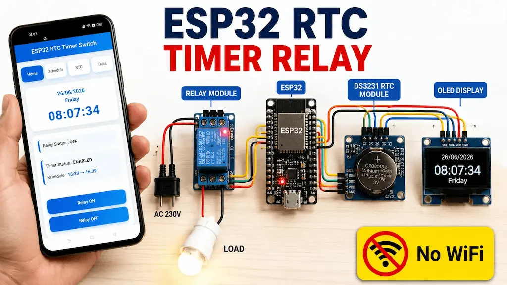
In this tutorial, we will build an ESP32 RTC Timer Relay Switch using the DS3231 RTC module, Relay Module, OLED Display, and a mobile-friendly Web Dashboard. The project works completely offline, so no WiFi router or Internet connection is required.

The ESP32 creates its own WiFi Access Point (AP), allowing you to connect your smartphone directly to the device. From the web dashboard, you can manually control the relay, synchronize the RTC with your phone, and configure a weekly timer schedule with just a few taps.
The DS3231 RTC provides accurate timekeeping, while the ESP32 stores all settings in its internal Preferences (Flash Memory). This project is ideal for automating home lights, water pumps, garden lights, aquarium lights, shop signboards, and many other time-based applications.
Table of Contents
Why Use an RTC Module Instead of ESP32 Internal Timer?
The ESP32 has an internal timer, but it loses the correct time whenever power is removed or the device restarts. An RTC module such as the DS3231 contains its own battery backup and continues counting time even when the ESP32 is switched off.
Because of this, the relay schedule always remains accurate after power restoration.
Some advantages of using the DS3231 RTC are:
- Very high time accuracy
- Battery backup support
- Works completely offline
- No Internet time synchronization required
- Reliable long-term operation
- Ideal for automation projects
Tutorial video on ESP32 RTC Relay Project
Features of the ESP32 RTC Timer Relay Switch
This project includes many useful features that are normally available only in commercial timer controllers.

Main Key Features:
- ESP32 based DS3231 Real-Time Clock
- Mobile Friendly Web Dashboard
- ESP32 Access Point Mode so No WiFi Router & No Internet Required
- Weekly Timer Scheduler & Individual Day Selection
- Manual Relay Control with Push Button or Wall Switch Support
- OLED Display
- One-click RTC Synchronization
- Automatic Recovery after Power Failure with Preferences Storage (EEPROM)
- Factory Reset
- Beginner Friendly User Interface
Required Components for ESP32 RTC Project:

- ESP32 DevKIT V1 Amazon
- DS3231 RTC module
- 1-channel 5V SPDT Relay Module Amazon
- 0.96-inch I2C OLED Display (optional)
- AC-DC converter (5V) HLK-5m05 (optional)
- 25uF DC capacitor (optional)
Circuit of the ESP32 DS3231 RTC Timer Relay
Now it’s time to assemble the hardware. Connect the ESP32, DS3231 RTC module, Relay Module, OLED Display, and Manual Switch according to the circuit diagram below.

I have used D25 GPIO to control the relay module.
The DS3231 module and OLED (optional) are connected with D22 & D21 GPIO.
For manual control, you can also connect a latched switch across the D13 and GND.
You can also connect a push-button across the D13 and GND as per the following circuit.

You can also use a 5V 5Amp mobile charger to supply the circuit instead of AC to DC converter.
Please take proper safety precautions while connecting the AC appliances.
Understanding the ESP32 RTC Timer Circuit
Before uploading the code, let’s understand how this ESP32 RTC Timer Relay Switch works.
When the ESP32 powers on, it initializes the DS3231 RTC module, OLED Display, Relay Module, and Web Server. The ESP32 then creates its own WiFi Access Point (AP), allowing your smartphone to connect directly without using a WiFi router.
The DS3231 continuously provides the current date and time to the ESP32. Every minute, the ESP32 compares the current time with the user-configured ON and OFF schedule. If the current time matches the programmed schedule, the relay automatically changes its state.

The OLED display shows the current time, date, day, relay status, and scheduled ON/OFF timings, while the web dashboard allows you to configure all settings from your mobile phone.
Since all settings are stored in the ESP32’s internal Preferences (Flash Memory), the timer schedule remains saved even after a power failure or restart.
PCB for this ESP32 DS3231 Project

You can also use the following PCB for this ESP32 project.
Now you can easily order your own custom-designed PCB from PCBWay at very reasonable prices.
Program ESP32 with Arduino IDE
In the Tutorial video, I have explained all the steps to program the ESP32 using Arduino IDE.
- Update the Preferences –> Additional boards Manager URLs: https://dl.espressif.com/dl/package_esp32_index.json, http://arduino.esp8266.com/stable/package_esp8266com_index.json
- Then install the ESP32 board from the Board Manager or Click Here to download the ESP32 board.
- Download the required libraries as mentioned in the code:
Source Code for the ESP32 RTC Relay module
After downloading, extract the ZIP archive and open the Arduino sketch in the Arduino IDE.
Configure the User Settings
Before uploading the sketch, open the Arduino code and review the User Configuration section. These settings allow you to customize the project according to your hardware and requirements.
//======================================================
// USER CONFIG
//======================================================

#define RELAY_ACTIVE_LOW      false
#define USE_PUSH_BUTTON       false
#define USE_PREFERENCES       true
#define SERIAL_DEBUG          true
- RELAY_ACTIVE_LOW: Set to
trueif you are using an Active LOW relay module; otherwise set it tofalsefor an Active HIGH relay. - USE_PUSH_BUTTON: Set to
trueto use a momentary push button, orfalseto use a latched wall switch. - USE_PREFERENCES: Leave this as
trueto save the timer settings in the ESP32 Flash Memory, so they remain after a restart or power failure. - SERIAL_DEBUG: Set to
trueto view debugging messages in the Serial Monitor. You can change it tofalseafter testing.
You can also customize the ESP32 WiFi Access Point name and password.
//======================================================
// WIFI AP CONFIG
//======================================================

#define AP_SSID      "ESP32_Timer"
#define AP_PASSWORD  "12345678"
After uploading the code, connect your smartphone to this WiFi network to access the web dashboard. You can change the SSID and password to any name and password of your choice before uploading the sketch.
Upload the ESP32 RTC Sketch
Open the Arduino sketch in the Arduino IDE and select your ESP32 board from the Tools → Board menu.
Next, select the correct COM port and click the Upload button.
After the upload is complete, open the Serial Monitor and set the baud rate to 115200.
If everything is connected correctly, the ESP32 will start its own WiFi Access Point and display the device information in the Serial Monitor.
Connect to the ESP32 Access Point
After the ESP32 starts, it creates a WiFi Access Point.
Open the WiFi settings on your smartphone and connect to the following network:
WiFi Name (SSID):
ESP32_TimerOnce connected, open any mobile browser and enter the following IP address:
http://192.168.4.1
The ESP32 RTC Timer Relay Switch Web Dashboard will open automatically.
Since the ESP32 works in Access Point (AP) mode, no WiFi router or Internet connection is required.
Open the Mobile Dashboard
The web dashboard is fully responsive and works on both Android and iPhone browsers.
It consists of four easy-to-use tabs.
Home
The Home page displays:
- Current Date
- Current Day
- Current Time
- Relay Status
- Timer Status
- Scheduled ON/OFF Time
- Manual Relay Control

Schedule
From the Schedule tab, you can:
- Enable or Disable the Timer
- Set Relay ON Time
- Set Relay OFF Time
- Select Operating Days
- Save the Weekly Schedule

RTC
The RTC page displays the current RTC Date, Time, and Day.

Simply tap Sync RTC With Phone to update the DS3231 RTC with your smartphone’s current date and time.
Tools
The Tools page provides:
- Restart ESP32
- Factory Reset
- Device Information

After configuring the timer schedule and synchronizing the RTC, the ESP32 RTC Timer Relay Switch is ready to operate automatically according to your programmed ON and OFF timings.

You can always control the relay with the manual switch.
ESP32 RTC Arduino Source Code Overview
The program is divided into several functions, making the code easy to understand, maintain, and modify. Below is a brief explanation of the major functions used in this project.
setup()
The setup() function runs only once when the ESP32 powers on or restarts. It initializes the Serial Monitor, GPIO pins, OLED display, DS3231 RTC module, relay, Preferences storage, WiFi Access Point, and Web Server. It also loads the previously saved timer settings and checks whether the relay should already be ON based on the current time.
loop()
The loop() function runs continuously throughout the program. It processes incoming web requests, updates the current time and OLED display, checks the manual switch, executes the timer scheduler, and monitors the factory reset button.
startAccessPoint()
This function configures the ESP32 to operate in Access Point (AP) mode. It creates a WiFi network using the user-defined SSID and password, allowing a smartphone or computer to connect directly to the ESP32 without requiring a WiFi router or Internet connection.
startWebServer()
This function creates all the HTTP routes used by the Web Dashboard. Each URL request is linked to a corresponding handler function, allowing the dashboard to display information, control the relay, save schedules, synchronize the RTC, restart the ESP32, and perform a factory reset.
handleRoot()
Whenever a user opens the ESP32 IP address in a browser, this function sends the complete HTML dashboard stored inside the ESP32 program memory.
handleStatus()
This function reads the current date and time from the DS3231 RTC module and sends the relay status, timer status, current date, current time, and current day to the web dashboard in JSON format. The dashboard automatically refreshes this information every second.
handleGetSchedule()
This function sends the currently saved timer settings, including the ON time, OFF time, timer status, and selected weekdays, to the Schedule page of the dashboard.
handleSaveSchedule()
When the user presses the Save Schedule button, this function receives all timer settings from the dashboard, updates the schedule structure, stores the values in ESP32 Preferences, refreshes the OLED display, and returns a confirmation message.
handleSetRTC()
This function synchronizes the DS3231 RTC with the current date and time received from the user’s smartphone. As a result, there is no need to manually set the RTC time in the Arduino sketch.
handleRelayOn() and handleRelayOff()
These functions provide manual relay control from the Home page of the dashboard. When either button is pressed, the relay state changes immediately, regardless of the timer schedule.
relayWrite()
This is the central relay control function used throughout the project. It handles both Active HIGH and Active LOW relay modules, updates the relay status, controls the timer indicator LED, refreshes the OLED display, and prints debugging messages to the Serial Monitor.
saveSettings()
This function stores all timer settings in the ESP32’s internal Flash Memory using the Preferences library. The saved configuration remains available even after power loss or restart.
loadSettings()
During startup, this function reads all previously saved settings from the ESP32 Preferences and restores the timer configuration automatically.
schedulerTask()
This is the heart of the timer system. Every minute, it reads the current time from the DS3231 RTC, compares it with the configured ON and OFF times, verifies that the current day is selected, and automatically switches the relay when the schedule matches.
checkScheduleAtStartup()
Whenever the ESP32 restarts, this function immediately checks whether the relay should already be ON or OFF according to the current time. This ensures that the relay resumes the correct state after a power failure without waiting for the next timer event.
isScheduleActive()
This helper function determines whether the relay should currently be active. It supports both normal schedules (ON time before OFF time) and overnight schedules (for example, ON at 10:00 PM and OFF at 6:00 AM).
processTimerEvent()
This function executes the actual timer event. It updates the relay state and records whether the relay was switched ON or OFF by the scheduler.
handleSwitch()
This function continuously monitors the manual switch connected to the ESP32. It supports both latched wall switches and momentary push buttons, including software debounce for reliable operation. Any manual operation temporarily overrides the automatic timer.
printTime()
Every second, this function reads the current time from the DS3231 RTC, updates the OLED display variables, prints the current date and time to the Serial Monitor, and refreshes the OLED screen.
updateOLED()
This function controls the OLED display. It alternates between two screens every five seconds. The first screen displays the current time, day, and date, while the second screen shows the relay status along with the configured ON and OFF schedule.
checkFactoryReset()
This function monitors the ESP32 BOOT button. If the button is held for the configured duration, all saved timer settings are erased from the ESP32 Preferences, and the device automatically restarts with the default configuration.
factoryReset()
This function clears all saved data from the ESP32’s non-volatile memory and reboots the system, allowing users to restore the project to its factory settings.
Overall Program Flow
The complete project follows the workflow shown below:
Power ON → Initialize Hardware → Create WiFi Access Point → Start Web Server → Load Saved Settings → Check Current Schedule → Wait for User Commands → Update OLED → Execute Weekly Timer → Save New Settings → Repeat
Conclusion
In this tutorial, we built a complete ESP32 RTC Timer Relay Switch using the DS3231 RTC module, Relay Module, OLED Display, and a mobile-friendly Web Dashboard. The project works completely offline, allowing you to configure and control the timer directly from your smartphone without requiring a WiFi router or Internet connection.
The DS3231 RTC ensures accurate timekeeping, while the ESP32 stores all timer settings in its internal Flash Memory, so the schedule remains safe even after a power failure. With features like weekly scheduling, one-click RTC synchronization, manual relay control, OLED status display, push button or wall switch support, and factory reset, this project is both beginner-friendly and suitable for real-world automation applications.
I hope you found this project helpful. If you have any questions or suggestions, feel free to leave a comment below. Don’t forget to watch the complete video tutorial and subscribe to Tech StudyCell for more ESP32, Arduino, IoT, and electronics projects.
Click Here for more such ESP32 projects.


