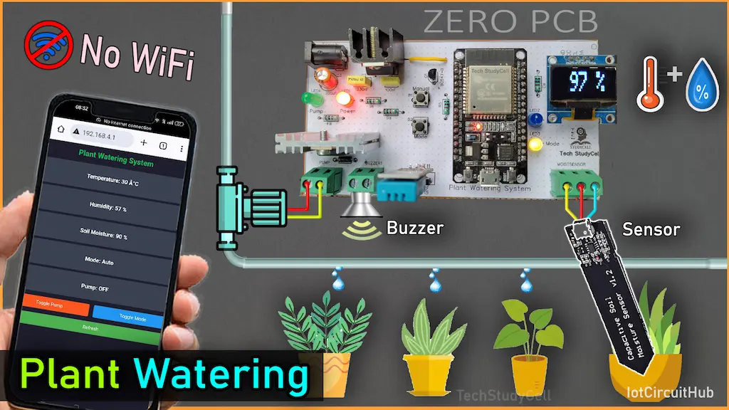
In modern agriculture and home gardening, automation is vital in ensuring plants receive the right amount of water without human intervention. This automatic plant watering project using ESP32 web server is designed to monitor soil moisture, temperature, and humidity while providing an automated watering mechanism. With an OLED display for real-time data visualization and a web interface for remote control, this project makes plant care efficient and hassle-free.

So if you follow all the steps, you can easily make this automatic plant monitoring system using ESP32 and soil moisture sensor.
Table of Contents
Required Components for Plant Watering Project

- ESP32 DEV KIT V1
- Capacitive soil moisture sensor V2.0
- DHT11 Sensor
- 0.96″ OLED Display
- 1k 0.25watt Resistors (R1-R6) – 6 no
- 1N4007 diode
- BC547 NPN Transistor
- TIP122 NPN Transistor with heat sink
- LEDs 5mm – 4no
- 7805 voltage regulator with heat sink
- 2-pin Push Button – 2no
- 2-pin Terminal connectors (2 no)
- 3-pin Terminal connectors (1 no)
- 5V DC Buzzer
- 100uF 25V capacitor (C1)
- 100nF 330nF AC capacitors (C1, C2)
- 12V DC pump or solenoid valve
- 12VDC Supply
Circuit of ESP32 Plant Watering project

In the circuit, you have to give a stable 12V DC supply. The amps rating of the power supply will depend on the pump or solenoid valve current rating.
A 7805 voltage regulator is used to provide the 5V supply to ESP32, and the 3.3V supply is given to the OLED and capacitive moisture sensor from the ESP32 3.3V pin.
To control the pump we have used a TIP122 NPN transistor which is connected with the GPIO D25.
Please refer to the following table for the ESP32 GPIO used in this circuit.
| ESP32 GPIOs | Connected Sensors/Components |
| D34 | Capacitive moisture sensor AOUT pin |
| D32 | Push-Button to turn ON/OFF pump |
| D33 | Push-Button for changing MODE. |
| D25 | TIP122 base pin (controlling pump) |
| D26 | BC547 base pin (controlling Buzzer) |
| D14 | DHT11 sensor O/P pin |
| D15 | LED indicator for MODE |
| D2 | LED indicator for WiFi |
| D21 | SDA of OLED |
| D22 | SCL of OLED |
If you want to use a 12V solenoid valve to control the water, then refer to the following circuit.

Please use heat sinks with TIP122 and 7805 voltage regulator.
Tutorial video on Automatic Plant Watering System
Features
- Real-time Soil Moisture Monitoring: Ensures plants receive the right amount of water.
- Temperature & Humidity Monitoring: Displays environmental data using a DHT11 sensor.
- OLED Display: Provides a compact and clear visualization of sensor readings.
- Web-Based Control Panel: Allows users to monitor and control the system remotely.
- Buzzer Alerts: Notifies when soil moisture is critically low.
- Automatic & Manual Modes: Users can choose between hands-free operation or manual control
Working Principle
This smart watering system works in two modes:
1. Automatic Mode
- The soil moisture sensor continuously monitors soil conditions.
- If the moisture level drops below the preset low threshold (e.g., 20%), the pump turns ON to supply water.
- Once moisture reaches the high threshold (e.g., 80%), the pump turns OFF.
- Temperature and humidity readings from the DHT11 sensor are displayed on the OLED screen.
- Users can access real-time sensor data via a WiFi-enabled web interface.
2. Manual Mode
- The user can manually turn the water pump ON or OFF using the web interface or a physical button.
- The system provides buzzer alerts when soil moisture is too low.
- The mode can be switched between automatic and manual via a button or web interface.
PCB Layout for ESP32 Plant Monitoring System


Please download the PCB layout, then print it on the A4 page.
Please check the PCB size while printing, it should be the same as mentioned in the Layout.
Homemade PCB for DIY Plant Watering system

In the tutorial video, I have explained, how you can easily make the complete circuit on zero PCB using the PCB Layout.
PCB for the Plant watering project
You can also download the PCB Gerber file and order the PCB from PCBWay.

About PCBWay and their services
You can order any custom-designed PCBs from PCBWay at very reasonable prices.

PCBWay not only produces FR-4 and Aluminum boards but also advanced PCBs like Rogers, HDI, and Flexible and Rigid-Flex boards, at very affordable prices.
For the online instant quote page please visit – pcbway.com/orderonline
You can also explore different PCB projects from their Open-source community pcbway.com/project/.
Source Codes for ESP32 Plant Monitoring System
Click on the following button to download the source codes for this ESP32 project.
Program ESP32 with Arduino IDE
For this IoT-based project, I have used the Arduino IDE to program ESP32.
First update the Preferences –> Aditional boards Manager URLs: https://raw.githubusercontent.com/espressif/arduino-esp32/gh-pages/package_esp32_dev_index.json, http://arduino.esp8266.com/stable/package_esp8266com_index.json
- Then install the ESP32 board (3.1.1) from the Board Manager or Click Here to download the ESP32 board.
- Download the required libraries from the following links:
- AceButton Library (Version 1.10.1)
- Adafruit_SSD1306 Library (Version 2.5.13)
- Adafruit Unified Sensor Library (Version 1.1.15)
- DHT Library (Version 1.4.6)
Get Sensor reading for the DRY & WET soil
To get the MIN & MAX moisture reading from the sensor, first, upload the following code to ESP32.
#define SensorPin       34  //D34
int     sensorVal;

void setup() {
  // Set up serial monitor
  Serial.begin(115200);
}

void loop() {
  sensorVal = analogRead(SensorPin);
  Serial.print("Moisture Value: ");
  Serial.println(sensorVal);
  delay(1000);
}
Connect the Moisture Sensor AOUT pin with D34 and supply 3.3V across VCC and GND.
Then open the serial monitor with baud rate 115200.

Note the MAX value when the sensor is dry, then dip the sensor into water and note the MIN value.
Save these two values.
Now open the main sketch in Arduino IDE and update the following values.
Update the MAX value when the sensor is dry, and the MIN value for the wet soil.
int wetSoilVal = 1050 ;  //min value when soil is wet
int drySoilVal = 3050 ;  //max value when soil is dry
With these two readings, we will calculate the moisture percentage.
After making these changes, please upload the code to ESP32.
Here’s a line-by-line explanation of the code:
1. Importing Required Libraries
#include <WiFi.h>
#include <WebServer.h>
#include <Adafruit_SSD1306.h>
#include <DHT.h>
#include <AceButton.h>
using namespace ace_button;- WiFi.h → Enables ESP32 to act as an Access Point (AP).
- WebServer.h → Helps in setting up a web server to control and monitor the system remotely.
- Adafruit_SSD1306.h → Controls the 0.96″ OLED display.
- DHT.h → Reads temperature and humidity from the DHT11 sensor.
- AceButton.h → Handles button press events efficiently.
2. Defining Constants and Initializing Components
#define SCREEN_WIDTH 128
#define SCREEN_HEIGHT 32
#define OLED_RESET -1
Adafruit_SSD1306 display(SCREEN_WIDTH, SCREEN_HEIGHT, &Wire, OLED_RESET);- Defines the width and height of the OLED screen.
- Initializes the SSD1306 OLED display.
define SensorPin 34
#define DHTPin 14
#define RelayPin 25
#define wifiLed 2
#define RelayButtonPin 32
#define ModeSwitchPin 33
#define BuzzerPin 26
#define ModeLed 15- Defines GPIO pins used for moisture sensor, DHT11, relay (pump), buzzer, mode LED, and buttons.
#define DHTTYPE DHT11
DHT dht(DHTPin, DHTTYPE);- Defines the DHT11 sensor type and initializes the sensor.
ButtonConfig config1;
AceButton button1(&config1);
ButtonConfig config2;
AceButton button2(&config2);- Configures two buttons using the AceButton library.
3. Setting Up WiFi (ESP32 as Access Point)
const char *ssid = "ESP32_Plant_System";
const char *password = "12345678";
WebServer server(80);- Sets up the ESP32 as an Access Point with a default SSID and password.
- The ESP32 runs a web server on port 80.
4. Moisture Sensor Calibration
int wetSoilVal = 1050;
int drySoilVal = 3050;- Defines sensor readings for wet and dry soil.
- 1050 → Sensor value when soil is wet.
- 3050 → Sensor value when soil is dry.
int moistPerLow = 20;
int moistPerHigh = 80;- Sets ideal moisture range (in percentage):
- Below 20% → Soil is too dry, pump should turn on.
- Above 80% → Soil is too wet, the pump should turn off.
5. Variables for System State
int sensorVal;
int moisturePercentage;
bool toggleRelay = LOW;
bool prevMode = true;
int temperature1 = 0;
int humidity1 = 0;
String currMode = "A";- Stores sensor values and system state:
sensorVal→ Raw moisture sensor reading.moisturePercentage→ Calculated soil moisture percentage.toggleRelay→ Tracks relay (pump) state (ON/OFF).prevMode→ Stores Auto (true) / Manual (false) mode.temperature1,humidity1→ Store DHT11 temperature & humidity values.
6. Web Page Handling
Creating Web Page
void handleRoot() {
    String html = "<!DOCTYPE html><html><head><title>Plant Monitor</title>";
    html += "<style>body { text-align:center; font-family:Arial; background:#1e1e2e; color:white; }";
    html += "h1 { color:#00c853; } .container { margin:auto; width:80%; } .box { padding:20px; border-radius:10px; margin:10px; background:#3b4252; }";
    html += ".button { padding:15px 30px; margin:10px; border:none; border-radius:5px; font-size:20px; cursor:pointer; display:inline-block; width:45%; }";
    html += "#pumpBtn { background:#ff5722; color:white; } #modeBtn { background:#2196F3; color:white; } #refreshBtn { background:#4CAF50; color:white; width:100%; }";
    html += "</style></head><body>";
    html += "<div class='container'><h1>Plant Watering System</h1>";
    html += "<div class='box'><h2>Temperature: " + String(temperature1) + " °C</h2></div>";
    html += "<div class='box'><h2>Humidity: " + String(humidity1) + " %</h2></div>";
    html += "<div class='box'><h2><b>Soil Moisture: " + String(moisturePercentage) + " %</b></h2></div>";
    html += "<div class='box'><h2>Mode: " + String(prevMode ? "Auto" : "Manual") + "</h2></div>";
    html += "<div class='box'><h2>Pump: " + String(toggleRelay ? "ON" : "OFF") + "</h2></div>";
    html += "<button id='pumpBtn' class='button' onclick='togglePump()'>Toggle Pump</button>";
    html += "<button id='modeBtn' class='button' onclick='toggleMode()'>Toggle Mode</button>";
    html += "<br><button id='refreshBtn' class='button' onclick='refreshPage()'>Refresh</button>";
    html += "<script>function togglePump(){ fetch('/toggle'); } function toggleMode(){ fetch('/mode'); } function refreshPage(){ location.reload(); }</script>";
    html += "</div></body></html>";

    server.send(200, "text/html", html);
}- This function creates the webpage UI displaying:
- Temperature
- Humidity
- Soil Moisture
- Mode (Auto/Manual)
- Pump Status (ON/OFF)
- Buttons for toggling Pump & Mode
7. Moisture and Weather Data Collection
void getMoisture() {
    sensorVal = analogRead(SensorPin);
    moisturePercentage = map(sensorVal, drySoilVal, wetSoilVal, 0, 100);
    moisturePercentage = constrain(moisturePercentage, 0, 100);
}- Reads moisture sensor value and converts it into a percentage.
void getWeather() {
    temperature1 = dht.readTemperature();
    humidity1 = dht.readHumidity();
    if (isnan(temperature1) || isnan(humidity1)) {
        Serial.println("Failed to read from DHT sensor!");
        temperature1 = 0;
        humidity1 = 0;
    }
}- Reads temperature and humidity from DHT11.
8. Automatic Pump Control
void controlPump() {
    if (prevMode) {
        if (moisturePercentage < moistPerLow) {
            digitalWrite(RelayPin, HIGH);
            toggleRelay = HIGH;
        }
        if (moisturePercentage > moistPerHigh) {
            digitalWrite(RelayPin, LOW);
            toggleRelay = LOW;
        }
    }
}- In Auto Mode, turns the pump ON when soil is dry and OFF when soil is wet.
9. Loop Execution
void loop() {
    server.handleClient();
    unsigned long currentMillis = millis();
    if (currentMillis - previousMillis >= interval) {
        previousMillis = currentMillis;
        getMoisture();
        getWeather();
        updateOLED();
    }
    handleBuzzer();
    controlPump();
    button1.check();
    button2.check();
}- Handles Web Requests.
- Updates Sensor Data & OLED every 2 seconds.
- Controls Buzzer & Pump based on conditions.
Connect the Pump & Sensors with the PCB

Now connect the sensors, OLED, Pump, and 5V Buzzeras per the above diagram.
Here I have a 12V 2A DC supply, you have to use the power supply as per the pump amps rating.
Testing the DIY Plant Watering circuit

Before connecting the solenoid valve with the pipeline, I will recommend you to test the circuit for Dry and Wet soil scenarios.
If everything works fine, connect the solenoid valve with the main water pipeline of the drip irrigation system.
Now your plants will get water automatically whenever needed.
Applications
- Home Gardening: Helps automate watering for indoor/outdoor plants.
- Greenhouses: Maintains optimal soil moisture and climate conditions.
- Agriculture: Reduces manual labor and ensures efficient water use.
- Smart Irrigation Systems: Can be integrated with larger irrigation networks.
This ESP32-based smart plant watering system provides an efficient, automated solution to plant care. With real-time monitoring, WiFi-enabled remote access, and intelligent control mechanisms, this project helps conserve water, minimize plant stress, and ensure healthy growth. Whether for home gardens or commercial farms, this system is a step towards smart and sustainable agriculture.
I hope you like this smart plant monitoring system using the ESP32 Web Server.
Click Here for more such ESP32 projects.
Please do share your feedback.


