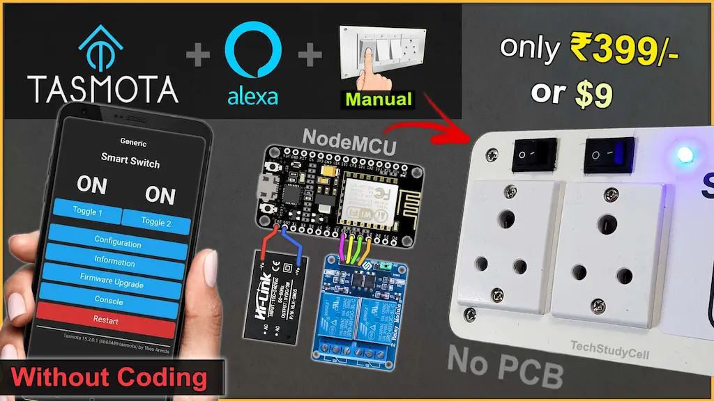
Building a smart home device no longer requires complex coding or expensive cloud services. In this project, we create an ESP8266 Tasmota Alexa Smart Plug using a free, no-code IoT platform that is perfect for beginners. By flashing Tasmota firmware on an ESP8266 NodeMCU, you can control electrical appliances using Amazon Alexa voice commands, a web dashboard, and even manual switches.

This DIY smart plug project is ideal for anyone who wants to learn IoT home automation in a simple, reliable, and cost-effective way.
Table of Contents
Why Choose Tasmota for This Project?
Tasmota is a free, open-source, and no-code firmware designed for ESP8266 and ESP32 devices. Unlike many IoT platforms, Tasmota works locally on your network and does not force you to depend on paid cloud services.
Key Benefits of Tasmota:
No coding required
Completely free and open source
Beginner-friendly web interface
Local control with fast response
Easy integration with Amazon Alexa
Supports relays, switches, LEDs, and sensors
For beginners, Tasmota is one of the best platforms to start with smart home automation.
In this project, an ESP8266 NodeMCU is flashed with Tasmota firmware and configured as a DIY Smart Plug. A relay module is used to control an electrical appliance, while Tasmota handles WiFi connectivity, device control, and Alexa integration.
You can control the smart plug using:
- Amazon Alexa voice commands
- Tasmota Web Dashboard
- Manual physical switch (optional)

Since Tasmota runs locally, the smart plug continues to work even if the internet is temporarily unavailable.
Required Components for DIY Smart Plug

- ESP8266 NodeMCU
- 2-Channel Relay Module (Active-LOW)
- 2 × Latched Switches (Toggle or Rocker)
- LED + 220Ω Resistor (WiFi indicator)
- AC socket (2 qty)
- 5V AC to DC converter
Circuit of the Smart Plug using NodeMCU

Pin Configuration
| Function | NodeMCU Pin | GPIO |
|---|---|---|
| Relay 1 | D5 | GPIO14 |
| Relay 2 | D6 | GPIO12 |
| Switch 1 | D1 | GPIO5 |
| Switch 2 | D2 | GPIO4 |
| WiFi LED | D0 | GPIO16 |
Note: Relays are active-LOW, meaning LOW = ON and HIGH = OFF.
The AC sockets are connected across the NO and COM terminals of the relays.
You can use any 5V 1Amp mobile charger to supply the circuit.
Please take proper safety precautions while working with High Voltage.
Tutorial video on Smart Plug using ESP8266 Tasmota
In the Internet of Things tutorial video, I have explained all the steps in detail for this ESP8266 smart plug
How the ESP8266 Tasmota Smart Plug Works
After flashing Tasmota, the ESP8266 connects to your WiFi network and provides a web-based control panel. GPIO pins are assigned to the relay, switch, and LED directly from the Tasmota interface—no programming required.
Once integrated with Amazon Alexa, you can control the plug using simple voice commands such as:
- “Alexa, turn ON switch1”
- “Alexa, turn OFF the switch1”
The relay state updates instantly, and the device status can be monitored from the Tasmota dashboard.
Download the required files to flash NodeMCU
You need the following files to flash the Tasmota firmware to the ESP8266 NodeMCU.
Here, I have used the tasmota.bin firmware for this project.
If you have a 32-bit system, download the tasmotizer_x86-1.2.exe instead of tasmotizer-1.2.exe from Github.
Now, to install the Tasmota firmware on NodeMCU ESP8266, please refer to the following article.
How to Install Tasmota on ESP8266: A Complete Beginner’s Guide
Now refer to the following picture to configure all the GPIOs according to the circuit.

Here, I have used an active-LOW relay module and latched switches, so I have used “Relay_i” and “Switch” respectively.
However, if you use an active-HIGH relay module and push-buttons, then you must select “Relay” and “Button“.
Here, the indicator LED is connected between D0 and GND. The LED logic works as follows: the LED turns ON whenever any relay is ON. If all relays are OFF and the WiFi is connected, the LED remains OFF. When all relays are OFF and the WiFi is not connected, the LED blinks to indicate the offline status.

After configuring the GPIOs now we can control the relays and monitor real-time feedback from the Tasmota web dashboard.
Alexa Integration with Tasmota
Tasmota supports Alexa control through built-in emulation and skills. You can interact with Tasmota devices using Amazon Alexa app through its Echo devices and also control the relay with voice commands.
Please refer to the following article for the step-by-step guide.

Here, I have named Relay-1 as “Switch1” and Relay-2 as “Switch2”. You can assign any name you prefer. Alexa will recognize and control each relay based on the name you give it.
After that, you can add the Tasmota devices to the Amazon Alexa app.

While adding the device, the NodeMCU, Echo dot, and mobile must be connected to the same Wi-Fi network.
Once connected, you can control the relays from a different network with the mobile, but the NodeMCU and Echo Dot must always be connected to the same WiFi network.

This makes the project truly hands-free and ideal for daily home use.
Offline & Manual Control with Switch

One major advantage of this project is offline reliability. Even if the internet goes down:
- The smart plug continues to work locally
- Manual switches still control the appliances
- No delay or lag in relay operation
This makes the system far more reliable than cloud-only IoT solutions.
PCBWay – Professional PCB Assembly Services
PCBWay offers fast, high-quality PCB assembly with lead times starting from 24 hours. Choose from Turn-key, Partial Turn-key, or Consigned options to match your project requirements.

You can also participate in the PCBWay 8th Project Design Contest
Global contest for innovators, engineers & makers
Three themes:
- Electronic Projects
- Mechanical Projects
- AIoT Projects (AI + IoT + Embedded Systems)

- Click “Participate Now” on PCBWay
- Or create a project in PCBWay Community and submit it under your chosen theme
- Projects must be original and submitted on time
- Multiple entries allowed
- Individuals or teams can participate
- Share complete design files (PCB, Gerber, BOM, schematics, CAD, code, etc.)
- PCBWay may showcase submitted projects with creator credit
Safety Considerations
⚠️ When working with AC mains electricity:
- Use properly rated relay modules
- Maintain electrical isolation
- Always use a secure enclosure
- Never touch live wires during testing

Safety is critical when building any smart plug project.
The ESP8266 Tasmota Alexa Smart Plug project demonstrates how easy it is to build a powerful home automation device using a free, no-code, and beginner-friendly IoT platform. With local control, voice commands, and simple configuration, Tasmota makes IoT accessible to everyone.
If you are starting your journey in IoT or smart home automation, this project is an excellent place to begin.


