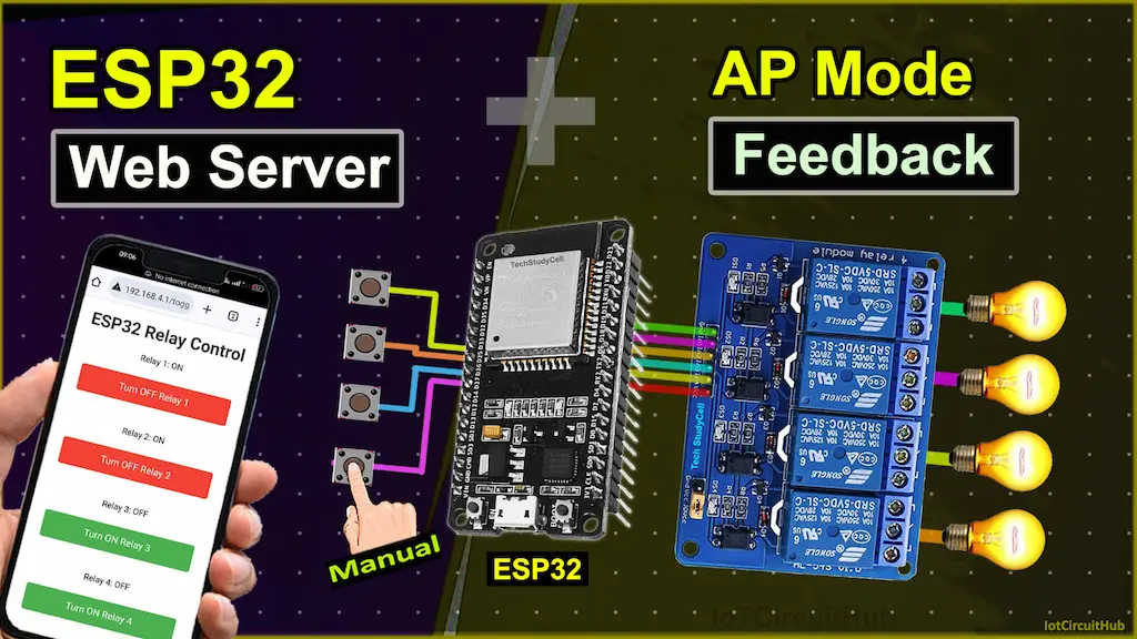
In this ESP32 Web Server tutorial, we’ll guide you through building a Wi-Fi-controlled relay system using the ESP32. The ESP32 will act as a web server and create its own Wi-Fi access point (AP), enabling you to control the relays via a web interface. Additionally, you can manually control the relays using pushbuttons.
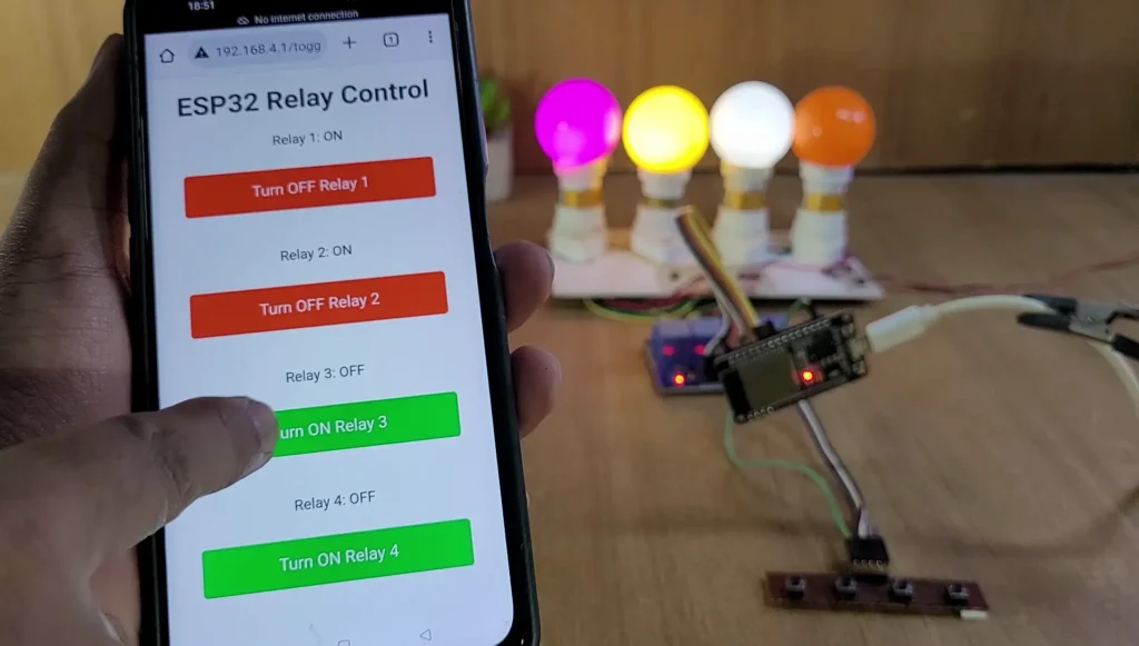
Table of Contents
Features:
- Wi-Fi Access Point: The ESP32 creates its own Wi-Fi hotspot, allowing you to connect and control the system without an external internet connection.
- Web Interface: A user-friendly web page is hosted by the ESP32 for controlling four relays.
- Manual Override: Physical pushbuttons provide local, manual control of the relays.
- Real-time Feedback: The web interface shows the current state of each relay and allows refreshing to update the status.
Tutorial Video on ESP32 Web Server Project
Required Components:
Circuit of the ESP32 Web Server project
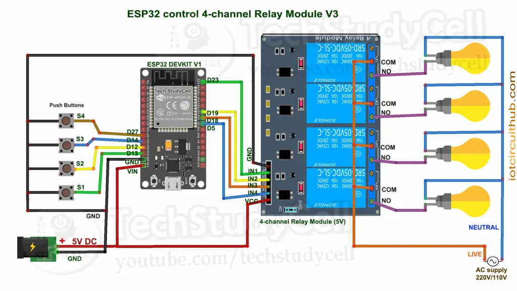
The circuit is very simple, I have used D23, D19, D18 & D5 GPIO to control the 4-channel relay module.
And, the GPIO D13, D12, D14 & D27 are connected with push buttons to control the relay module manually.
I have used the INPUT_PULLUP function in Arduino IDE instead of using the pull-up resistors with each push button.
As per the source code, when the control pins of the relay module receive a LOW signal the relay will turn on and the relay will turn off for the HIGH signal in the control pin.
I have used a 5V 5Amp mobile charger to supply the circuit.
Please take proper safety precautions while connecting the AC appliances.
Program ESP32 with Arduino IDE
In the tutorial video, I explained all the steps for programming the NodeMCU using Arduino IDE.
- Update the Preferences –> Aditional boards Manager URLs: https://dl.espressif.com/dl/package_esp32_index.json, http://arduino.esp8266.com/stable/package_esp8266com_index.json
- Then install the ESP32 board (version: 3.0.5) from the Board Manager or Click Here to download the ESP32 board.
- You need the following libraries:
- WiFi
- WebServer
Code for ESP32 Web Server control relay
#include <WiFi.h>
#include <WebServer.h>

// Wi-Fi access point credentials
const char* ssid = "ESP32_Hotspot";
const char* password = "12345678";

// Static IP configuration
IPAddress local_IP(192, 168, 4, 1);
IPAddress gateway(192, 168, 4, 1);
IPAddress subnet(255, 255, 255, 0);

// GPIO pins for relays (active low)
const int relayPins[] = {23, 19, 18, 5};

// GPIO pins for push buttons
const int buttonPins[] = {13, 12, 14, 27};

// Relay states
bool relayStates[] = {HIGH, HIGH, HIGH, HIGH}; // Start with relays off

// Create a WebServer object on port 80
WebServer server(80);

// Toggle relay function
void toggleRelay(int relayIndex) {
  relayStates[relayIndex] = !relayStates[relayIndex];
  digitalWrite(relayPins[relayIndex], relayStates[relayIndex]);
}

// HTML content generation function with feedback and styling
String generateHTML() {
  String html = "<!DOCTYPE html><html><head><meta name=\"viewport\" content=\"width=device-width, initial-scale=1.0\">";
  html += "<style>";
  html += "body { font-family: Arial, sans-serif; max-width: 400px; margin: auto; text-align: center; }";
  html += "h1 { color: #333; }";
  html += ".button { display: inline-block; width: 80%; padding: 15px; margin: 10px; font-size: 18px; color: white; background-color: #4CAF50; border: none; border-radius: 5px; text-decoration: none; }";
  html += ".button.off { background-color: #f44336; }";
  html += ".refresh { background-color: #2196F3; padding: 10px 20px; margin: 15px; color: white; font-size: 18px; border: none; border-radius: 5px; }";
  html += ".footer { margin-top: 20px; color: #666; font-size: 14px; }";
  html += "</style></head><body>";
  html += "<h1>ESP32 Relay Control</h1>";

  // Relay control buttons
  for (int i = 0; i < 4; i++) {
    html += "<p>Relay " + String(i+1) + ": " + (relayStates[i] == LOW ? "ON" : "OFF") + "</p>";
    html += "<form action=\"/toggle_relay_" + String(i) + "\" method=\"GET\">";
    html += "<button class=\"button " + String(relayStates[i] == LOW ? "off" : "") + "\" type=\"submit\">"
            + String(relayStates[i] == LOW ? "Turn OFF" : "Turn ON") + " Relay " + String(i+1) + "</button>";
    html += "</form><br>";
  }

  // Refresh button
  html += "<form action=\"/refresh\" method=\"GET\">";
  html += "<button class=\"refresh\" type=\"submit\">Refresh</button>";
  html += "</form>";

  // Footer text
  html += "<div class=\"footer\">Tech StudyCell</div>";

  html += "</body></html>";
  return html;
}

// Setup server routes
void setupServerRoutes() {
  // Route for the main page
  server.on("/", HTTP_GET, []() {
    server.send(200, "text/html", generateHTML());
  });

  // Route for relay toggle control
  for (int i = 0; i < 4; i++) {
    int relayIndex = i;
    server.on(("/toggle_relay_" + String(i)).c_str(), HTTP_GET, [relayIndex]() {
      toggleRelay(relayIndex);
      server.send(200, "text/html", generateHTML()); // Update the page with current states
    });
  }

  // Route for refreshing the page without toggling relays
  server.on("/refresh", HTTP_GET, []() {
    server.send(200, "text/html", generateHTML());
  });
}

void setup() {
  Serial.begin(115200);

  // Initialize relay pins as output and set them to HIGH (inactive for active-low relays)
  for (int i = 0; i < 4; i++) {
    pinMode(relayPins[i], OUTPUT);
    digitalWrite(relayPins[i], HIGH); // Start with relays off
  }

  // Initialize button pins as input with pull-up resistors
  for (int i = 0; i < 4; i++) {
    pinMode(buttonPins[i], INPUT_PULLUP);
  }

  // Configure Wi-Fi with a fixed IP and set up as an access point
  WiFi.softAPConfig(local_IP, gateway, subnet);
  WiFi.softAP(ssid, password);
  Serial.print("Access Point IP: ");
  Serial.println(WiFi.softAPIP());

  // Set up web server routes
  setupServerRoutes();

  // Start the server
  server.begin();
  Serial.println("Web server started.");
}

void loop() {
  // Handle incoming client requests
  server.handleClient();

  // Manual button control
  for (int i = 0; i < 4; i++) {
    if (digitalRead(buttonPins[i]) == LOW) { // Button pressed (active low)
      delay(100); // Debounce delay
      toggleRelay(i); // Toggle the corresponding relay
      while (digitalRead(buttonPins[i]) == LOW); // Wait until button is released
      delay(100); // Debounce delay
    }
  }
}
Here’s a detailed, line-by-line explanation of the code:
cppCopy code#include <WiFi.h>
#include <WebServer.h>
- Include Libraries:
WiFi.his used to configure the ESP32 as a Wi-Fi hotspot, whileWebServer.hallows us to create a basic web server to control relays.
cppCopy codeconst char* ssid = "ESP32_Hotspot";
const char* password = "12345678";
- Wi-Fi Credentials: These lines define the SSID (name) and password for the Wi-Fi network the ESP32 will create. Users will connect to this network to control the relays.
cppCopy codeIPAddress local_IP(192, 168, 4, 1);
IPAddress gateway(192, 168, 4, 1);
IPAddress subnet(255, 255, 255, 0);
- Static IP Configuration: Sets the ESP32’s IP address, gateway, and subnet for its network. The fixed IP
192.168.4.1makes it easy to access from any connected device.
cppCopy codeconst int relayPins[] = {26, 27, 32, 33};
const int buttonPins[] = {12, 13, 14, 15};
- Pin Definitions: Defines GPIO pins for four relays (
relayPins) and four buttons (buttonPins). Each relay will be controlled by a unique pin, and each button allows manual control of a relay.
cppCopy codebool relayStates[] = {HIGH, HIGH, HIGH, HIGH}; // Start with relays off
- Relay States Array: This array keeps track of each relay’s state (HIGH = OFF and LOW = ON, as relays are active-low). Initially, all are set to HIGH (OFF).
cppCopy codeWebServer server(80);
- Initialize Web Server: Creates a
WebServerobject on port 80, which is the default port for HTTP.
cppCopy codevoid toggleRelay(int relayIndex) {
  relayStates[relayIndex] = !relayStates[relayIndex];
  digitalWrite(relayPins[relayIndex], relayStates[relayIndex]);
}
- Toggle Relay Function: This function flips a relay’s state. When called with a relay index (0–3), it changes the relay state in
relayStatesand writes the new state to the GPIO pin, turning the relay ON or OFF.
cppCopy codeString generateHTML() {
- Generate HTML: Begins a function to create the HTML content displayed on the webpage, providing buttons for each relay and a refresh option.
cppCopy codeString html = "<!DOCTYPE html><html><head><meta name=\"viewport\" content=\"width=device-width, initial-scale=1.0\">";
html += "<style>body { font-family: Arial, sans-serif; max-width: 400px; margin: auto; text-align: center; }";
html += "h1 { color: #333; }";
html += ".button { display: inline-block; width: 80%; padding: 15px; margin: 10px; font-size: 18px; color: white; background-color: #4CAF50; border: none; border-radius: 5px; text-decoration: none; }";
html += ".button.off { background-color: #f44336; }";
html += ".refresh { background-color: #2196F3; padding: 10px 20px; margin: 15px; color: white; font-size: 18px; border: none; border-radius: 5px; }";
html += ".footer { margin-top: 20px; color: #666; font-size: 14px; }</style></head><body>";
html += "<h1>ESP32 Relay Control</h1>";
- HTML and CSS Styling: Starts building the HTML content with some styling to make the page responsive and visually appealing. Buttons are styled for ON (green) and OFF (red), and a “Refresh” button is blue.
cppCopy codefor (int i = 0; i < 4; i++) {
  html += "<p>Relay " + String(i+1) + ": " + (relayStates[i] == LOW ? "ON" : "OFF") + "</p>";
  html += "<form action=\"/toggle_relay_" + String(i) + "\" method=\"GET\">";
  html += "<button class=\"button " + String(relayStates[i] == LOW ? "off" : "") + "\" type=\"submit\">"
          + String(relayStates[i] == LOW ? "Turn OFF" : "Turn ON") + " Relay " + String(i+1) + "</button>";
  html += "</form><br>";
}
- Relay Buttons in HTML: For each relay, adds a paragraph displaying its state (ON/OFF) and a button to toggle it. The button sends a GET request to the server to toggle the specific relay.
cppCopy codehtml += "<form action=\"/refresh\" method=\"GET\">";
html += "<button class=\"refresh\" type=\"submit\">Refresh</button>";
html += "</form>";
html += "<div class=\"footer\">Tech StudyCell</div>";
html += "</body></html>";
return html;
}
- Refresh Button and Footer: Adds a button that reloads the page without changing relay states and displays footer text “Tech StudyCell.”
cppCopy codevoid setupServerRoutes() {
- Setup Server Routes: Begins setting up routes that the web server will handle.
cppCopy codeserver.on("/", HTTP_GET, []() {
  server.send(200, "text/html", generateHTML());
});
- Main Page Route: When users access
/, the ESP32 generates the HTML page withgenerateHTML()and sends it to the client.
cppCopy codefor (int i = 0; i < 4; i++) {
  int relayIndex = i;
  server.on(("/toggle_relay_" + String(i)).c_str(), HTTP_GET, [relayIndex]() {
    toggleRelay(relayIndex);
    server.send(200, "text/html", generateHTML());
  });
}
- Toggle Relay Routes: Sets up routes to toggle each relay. When a button is pressed, the corresponding relay toggles and the updated HTML is sent.
cppCopy codeserver.on("/refresh", HTTP_GET, []() {
  server.send(200, "text/html", generateHTML());
});
- Refresh Route: Refreshes the page to show relay statuses without toggling them.
cppCopy codevoid setup() {
  Serial.begin(115200);
- Setup Function: Initializes the ESP32, the relays, buttons, and Wi-Fi.
cppCopy codefor (int i = 0; i < 4; i++) {
  pinMode(relayPins[i], OUTPUT);
  digitalWrite(relayPins[i], HIGH);
}
- Initialize Relays: Sets each relay pin as an output and starts each relay in the HIGH (OFF) state.
cppCopy codefor (int i = 0; i < 4; i++) {
  pinMode(buttonPins[i], INPUT_PULLUP);
}
- Initialize Buttons: Sets button pins as inputs with pull-up resistors.
cppCopy codeWiFi.softAPConfig(local_IP, gateway, subnet);
WiFi.softAP(ssid, password);
Serial.print("Access Point IP: ");
Serial.println(WiFi.softAPIP());
- Start Wi-Fi Access Point: Configures the ESP32 as a Wi-Fi access point with the specified SSID, password, and static IP (
192.168.4.1).
cppCopy codesetupServerRoutes();
server.begin();
Serial.println("Web server started.");
}
- Initialize Web Server: Calls
setupServerRoutes()to define server routes, starts the server, and prints a confirmation message.
cppCopy codevoid loop() {
  server.handleClient();
- Handle Client Requests:
server.handleClient()continuously listens for incoming requests, such as relay toggle or refresh requests.
cppCopy codefor (int i = 0; i < 4; i++) {
  if (digitalRead(buttonPins[i]) == LOW) { // Button pressed (active low)
    delay(100); // Debounce delay
    toggleRelay(i); // Toggle the corresponding relay
    while (digitalRead(buttonPins[i]) == LOW); // Wait until button is released
    delay(100); // Debounce delay
  }
}
}
- Manual Button Control: Checks each button. When pressed (LOW), it toggles the associated relay. Debounce delays ensure stable input.
This code enables users to control relays via both the web interface and physical pushbuttons, with feedback on current relay states.
PCB for the ESP32 Projects
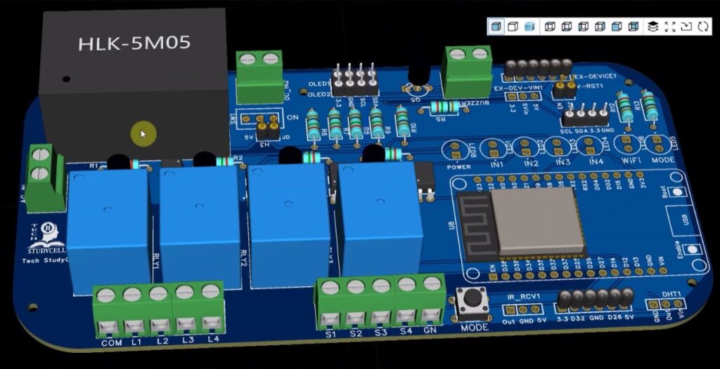
You can also use this PCB for this ESP32 IoT project. Just download the Gerber file and order the PCB from PCBWay.
You can order any custom-designed PCBs from PCBWay at very reasonable prices.

PCBWay not only produces FR-4 and Aluminum boards but also advanced PCBs like Rogers, HDI, and Flexible and Rigid-Flex boards, at very affordable prices.
For the online instant quote page please visit – pcbway.com/orderonline
You can also explore different PCB projects from their Open-source community pcbway.com/project/.
For more details please visit the following articles.
Why PCBway
Steps to Connect to ESP32 Access Point and Control Relays
Follow these steps to connect to the ESP32 Wi-Fi access point and control the relays using a web interface:
Step 1: Power Up the ESP32
Connect the ESP32 to a power source via USB or any 3.3V/5V power supply.
The ESP32 will automatically create a Wi-Fi access point.
Step 2: Connect to the ESP32 Wi-Fi Network
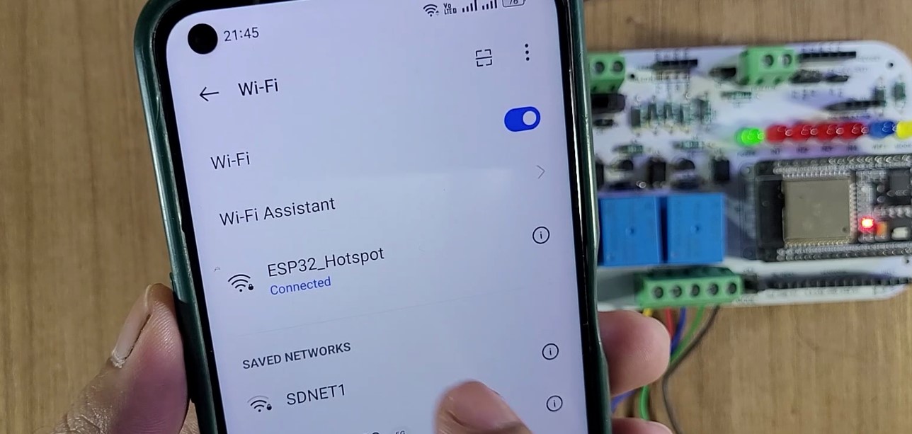
On your phone, tablet, or laptop, go to Wi-Fi Settings and search for available Wi-Fi networks.
Connect to the Wi-Fi network with the following credentials:
SSID:
ESP32_HotspotPassword:
12345678Once connected, your device will join the ESP32’s network.
Step 3: Open the Web Interface
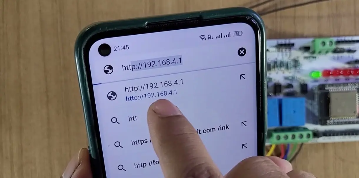
Open a web browser on your connected device (Chrome, Firefox, Safari, etc.).
In the browser’s address bar, type the following IP address and press Enter http://192.168.4.1
The ESP32 Relay Control Web Interface will load.
Step 4: Control the Relays
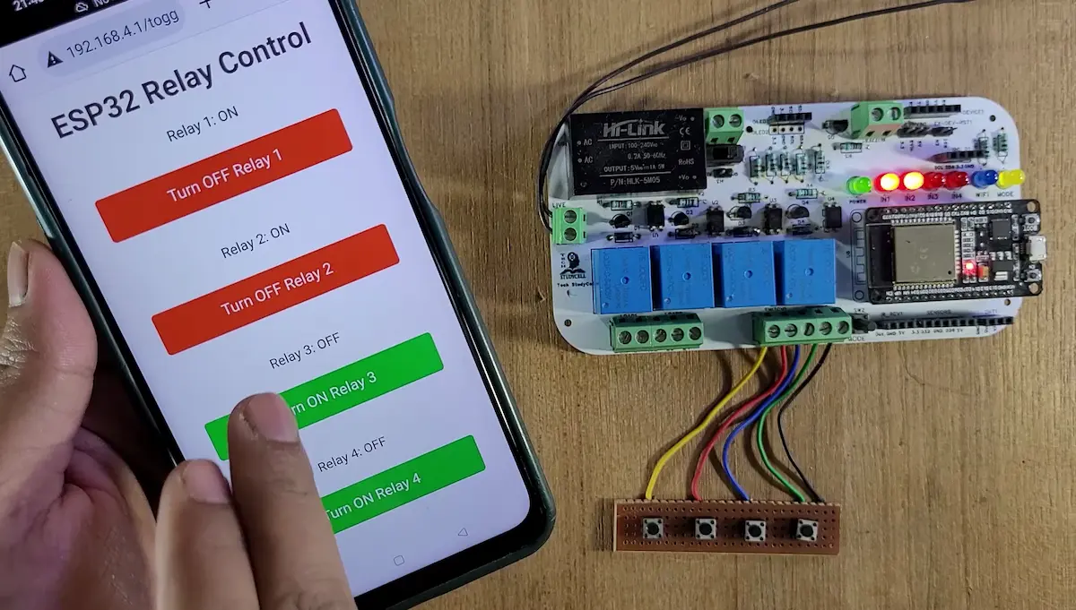
On the web interface, you will see four buttons labeled for each relay.
Tap or click the button to toggle the respective relay:
If the relay is OFF, pressing the button will turn it ON.
If the relay is ON, pressing the button will turn it OFF.
The current status of each relay will be displayed below the buttons.
Step 5: Refresh the Web Page
To update the current relay status, click the Refresh button on the web interface.
This will reload the page and show the real-time status of all relays.
Step 6: Manual Control (Optional)
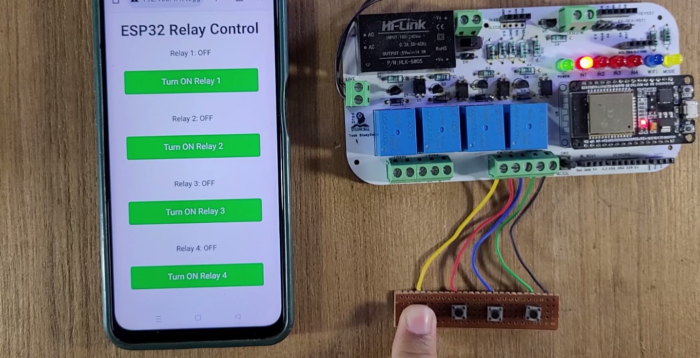
You can also manually control the relays using the pushbuttons connected to the ESP32.
Press a button to toggle the corresponding relay. The web interface will reflect the change after a refresh.
Notes
The ESP32 operates as an Access Point (AP) and does not require an internet connection.
The system is isolated and works within the Wi-Fi range of the ESP32.
Ensure that your device remains connected to the ESP32’s Wi-Fi network to control the relays.
I hope you like this Smart House IoT project idea with the Arduino Cloud ESP32.
Click Here for more such ESP32 projects.
Please do share your feedback on this IoT project. Thank you for your time.

