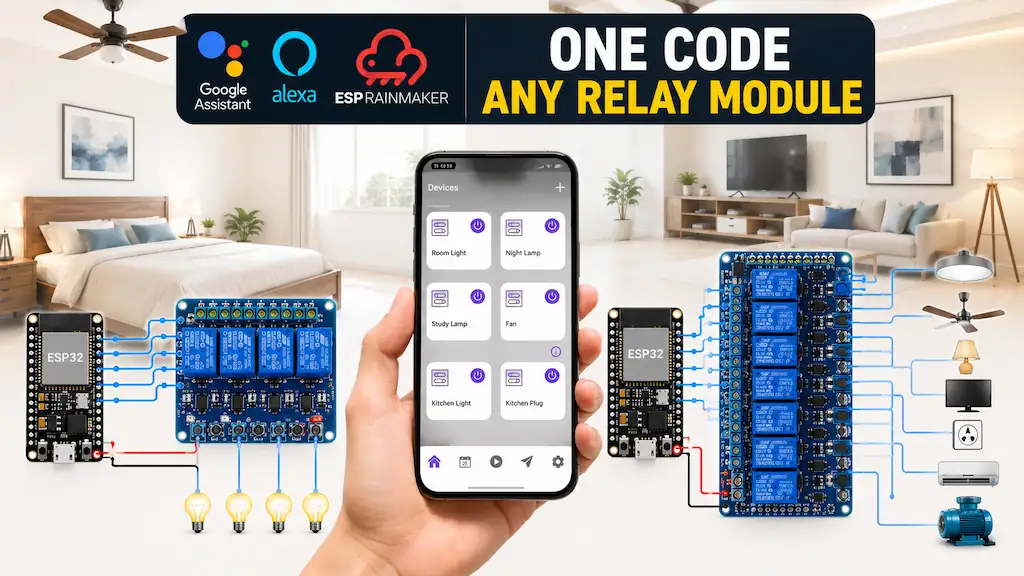

Building a smart home automation system using ESP32 and ESP RainMaker is now easier with this universal ESP32 home automation project. In this DIY IoT project, we use a single Arduino sketch to control 1, 2, 4, or 8-channel relay modules using the ESP RainMaker platform. Instead of maintaining separate programs for different relay boards, you only need to change the TOTAL_RELAYS configuration value. The system supports smartphone control, Google Home, Amazon Alexa, manual switches, BLE Wi-Fi provisioning, OTA firmware updates, scheduling, time-zone services, and EEPROM-based relay state storage. It is a flexible solution for anyone interested in ESP32 home automation, smart switches, and DIY IoT projects.
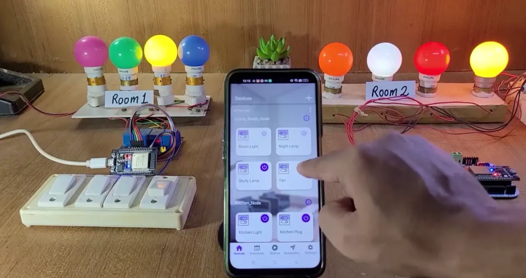
Table of Contents
Project Overview
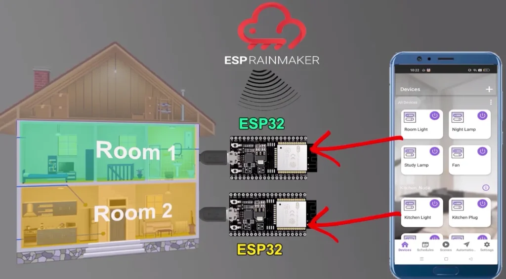
The ESP32 is a powerful microcontroller with built-in Wi-Fi and Bluetooth capabilities, making it suitable for smart home automation. By integrating it with ESP RainMaker, you can control connected electrical appliances through a compatible smartphone app and supported voice assistants.
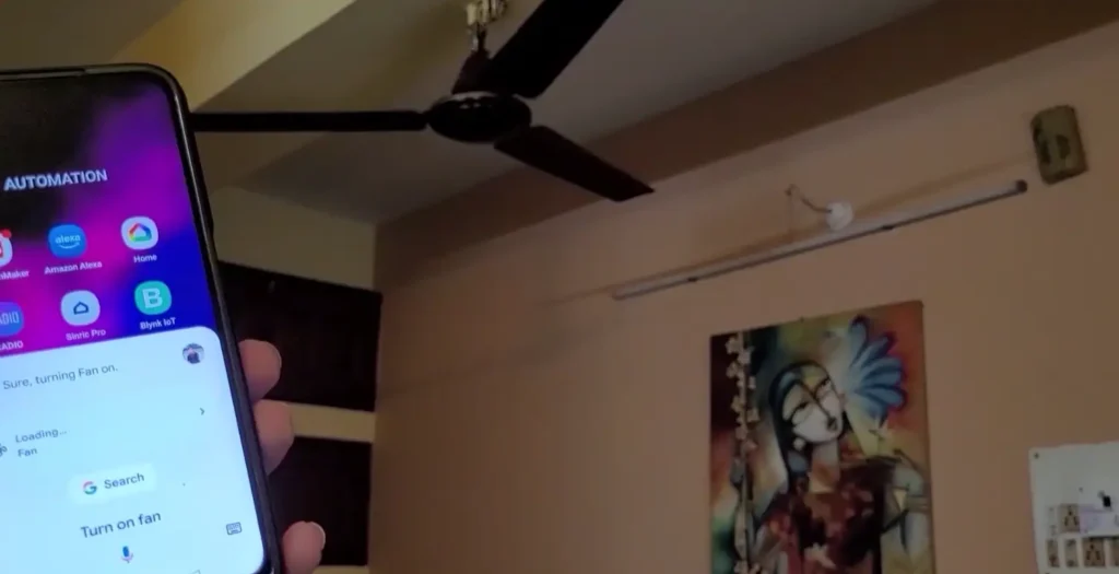
The main highlight of this project is its universal relay control code. The same program can be configured for different relay module sizes, from a single-channel relay to an eight-channel relay board.
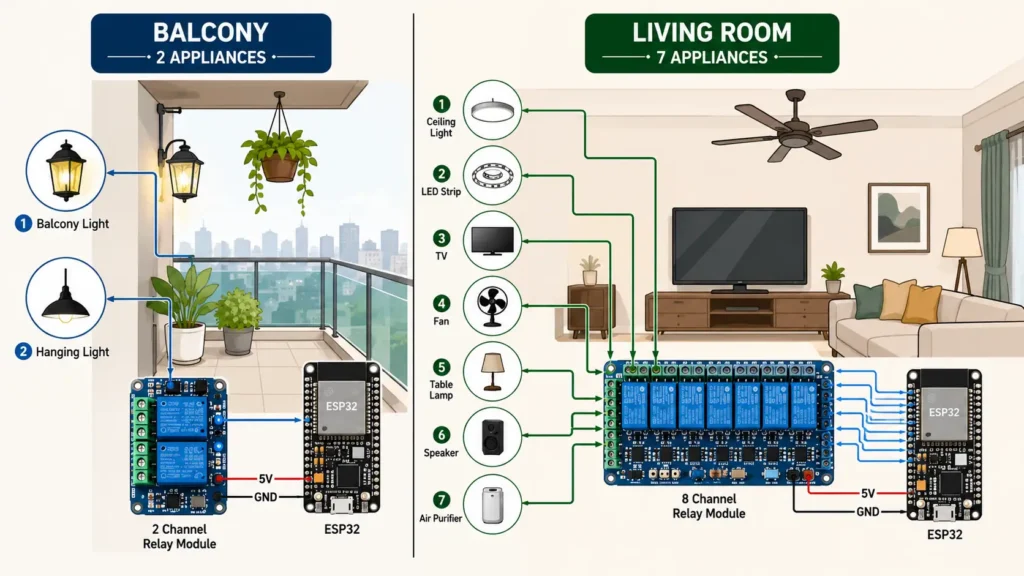
For example, you can use the same code to control a bedroom light, ceiling fan, night lamp, television power supply, or other suitable electrical loads. You can also expand the project when you need to control more appliances.
Tutorial video on the Universal ESP RainMaker Project
Key Features of the ESP32 ESP RainMaker Project
- One Universal Arduino Code: Supports 1, 2, 4, and 8-channel relay modules.
- ESP RainMaker Integration: Control appliances using the ESP RainMaker app and cloud platform.
- Google Home Support: Voice control through a compatible Google Home or Google Assistant setup.
- Amazon Alexa Support: Control compatible devices using Alexa.
- Manual Switch Control: Operate relays using physical switches or push buttons.
- BLE Wi-Fi Provisioning: Configure Wi-Fi through the provisioning process without hardcoding Wi-Fi credentials in the sketch.
- OTA Firmware Updates: Update supported firmware wirelessly.
- Scheduling: Configure supported schedules through ESP RainMaker.
- Time-Zone Service: Use the platform’s time-zone functionality for time-related features.
- EEPROM State Storage: Save relay states and restore them after a restart, when enabled.
- Active LOW and Active HIGH Support: Configure the code according to your relay module’s trigger logic.
- Push Button or Latched Switch: Select the switch operating mode in the configuration.
- Expandable Design: Add more relays by changing the configuration and wiring the corresponding inputs and outputs.
Note: Cloud control, voice assistants, provisioning, and OTA functionality depend on the relevant services, network connectivity, compatible software versions, and configuration.
Required Components
To build this ESP32 smart home automation system, you will need the following components.
- ESP32 Development Board (DOIT ESP32 DevKit V1 or compatible)
- 1, 2, 4 or 8 Channel Relay Module (Active LOW or Active HIGH)
- Push Buttons / Wall Switches
You do not need a separate ESP32 program for each relay board. The universal sketch can be configured for the number of relays you want to use.
Software Requirements
Install or prepare the following software and libraries before uploading the program:
- Arduino IDE
- ESP32 Arduino Board Package
- ESP RainMaker libraries included or supported by the ESP32 Arduino environment
- AceButton library for handling physical switch inputs
- EEPROM library available in the ESP32 Arduino environment
- ESP RainMaker mobile app for provisioning and control
The project code has been developed around the ESP32 Arduino environment, with ESP32 Arduino Core 2.0.14 used in the tested setup. If you use a different core version, verify library compatibility and test the complete system before installing it permanently.
After downloding the code, open it with Arduino IDE.
Universal Relay Configuration
One of the most useful features of this project is its simple configuration section. Instead of editing multiple functions to support a different relay board, you can set the required relay count in the sketch.
For example:
const uint8_t MAX_RELAYS = 8;
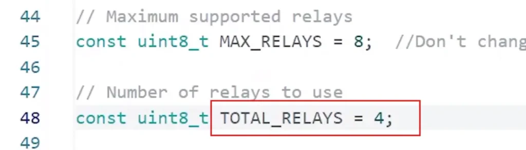
const uint8_t TOTAL_RELAYS = 4;

const bool RELAY_ACTIVE_LOW = true;
const bool USE_LATCHED_SWITCH = false;
const bool ENABLE_EEPROM = true;
Here is what these settings mean:
MAX_RELAYS: The maximum relay capacity supported by the current sketch. Keep it at 8 for this project.TOTAL_RELAYS: The number of relay channels you want to use.RELAY_ACTIVE_LOW: Set totruefor active-LOW relay modules orfalsefor active-HIGH modules, after verifying your board’s trigger logic.USE_LATCHED_SWITCH: Set totruefor the configured latched-switch behavior orfalsefor push-button operation.ENABLE_EEPROM: Enables or disables relay-state storage.
How to Select the Relay Module
| Relay Module | Configuration |
|---|---|
| 1-channel relay | TOTAL_RELAYS = 1 |
| 2-channel relay | TOTAL_RELAYS = 2 |
| 4-channel relay | TOTAL_RELAYS = 4 |
| 8-channel relay | TOTAL_RELAYS = 8 |
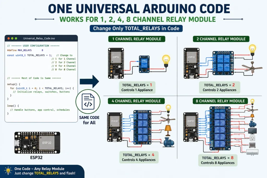
For example, if you want to control four appliances, set:
const uint8_t TOTAL_RELAYS = 4;For eight appliances, change the value to:
const uint8_t TOTAL_RELAYS = 8;After changing the setting, upload the sketch again. Ensure that the relay and switch GPIO arrays, wiring, and selected hardware match the channels you intend to use. The GPIO assignments in this project must also be suitable for your particular ESP32 board.
Circuit Connections
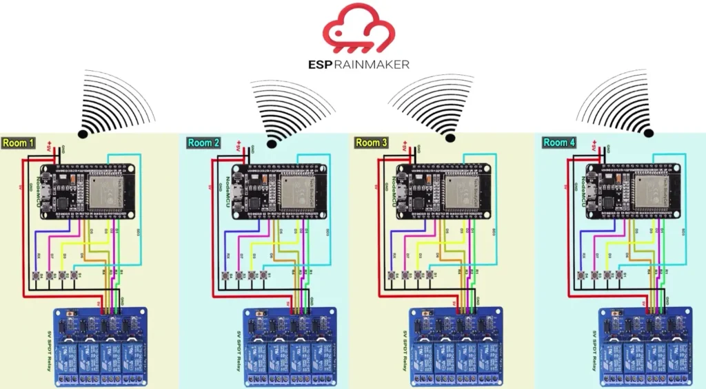
The ESP32 communicates with the relay module through its GPIO pins. Each relay output controls a connected load, while physical switches provide manual control.
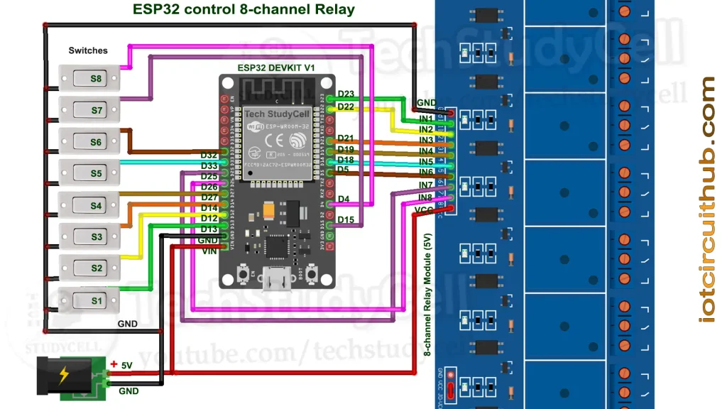
In the example configuration, the relay GPIO mapping is:
| Relay | ESP32 GPIO |
|---|---|
| Relay 1 | GPIO 23 |
| Relay 2 | GPIO 22 |
| Relay 3 | GPIO 21 |
| Relay 4 | GPIO 19 |
| Relay 5 | GPIO 18 |
| Relay 6 | GPIO 5 |
| Relay 7 | GPIO 25 |
| Relay 8 | GPIO 26 |
The corresponding physical switch GPIO mapping is:
| Switch | ESP32 GPIO |
|---|---|
| Switch 1 | GPIO 13 |
| Switch 2 | GPIO 12 |
| Switch 3 | GPIO 14 |
| Switch 4 | GPIO 27 |
| Switch 5 | GPIO 33 |
| Switch 6 | GPIO 32 |
| Switch 7 | GPIO 15 |
| Switch 8 | GPIO 4 |
The sketch uses INPUT_PULLUP for switch inputs, so the switches should be wired according to that configuration. Check the suitability of these pins for your exact board and peripherals before assembly.
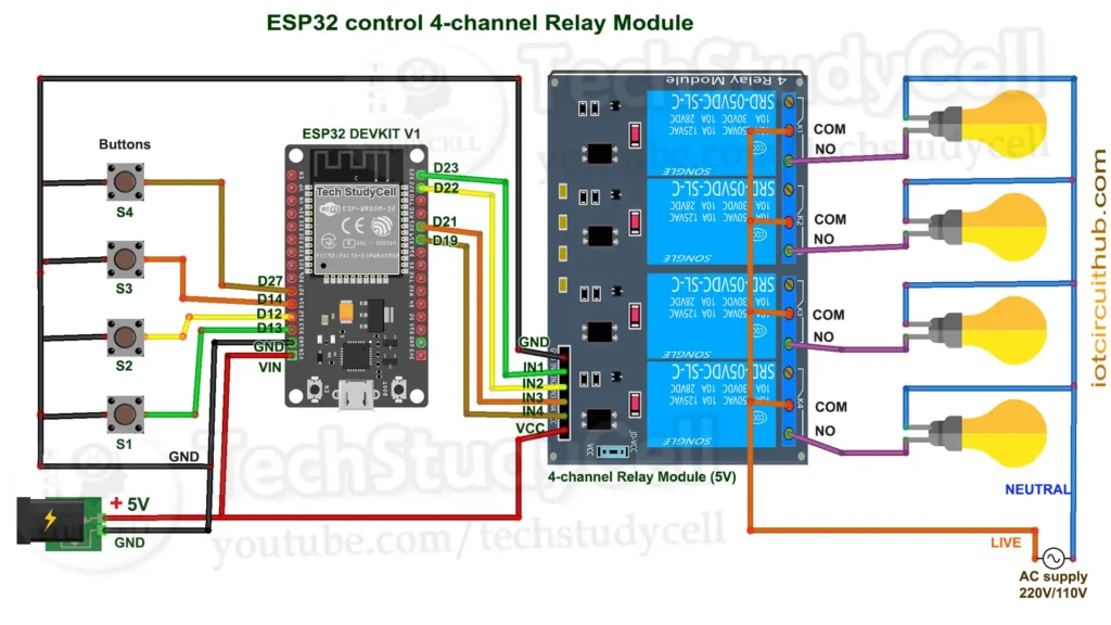
Important electrical safety note: Mains electricity can cause fatal electric shock or fire. Use relay modules with appropriate voltage and current ratings, proper insulation, an enclosure, strain relief, and suitable protection. Do not handle exposed mains wiring while powered. If you are unfamiliar with mains installations, have a qualified electrician complete the wiring. Never connect mains voltage directly to ESP32 GPIO pins.
How the ESP32 Home Automation System Works
The project combines the ESP32, ESP RainMaker, relay hardware, and physical switches into one home automation system.
Step 1: Configure the Code
Choose the number of relay channels you want to use by changing TOTAL_RELAYS. Configure the relay trigger logic, switch type, and EEPROM option according to your hardware and requirements.
Step 2: Connect the Hardware
Connect the ESP32 relay GPIO pins to the corresponding input pins on the relay module. Connect the physical switches to their configured GPIO pins and wire the appliances through appropriately rated relay contacts.
Step 3: Upload the Arduino Sketch
Select the correct ESP32 board and port in Arduino IDE, then compile and upload the program. During initialization, the sketch configures the GPIO pins and initializes the relay, switch, EEPROM, and ESP RainMaker functions.
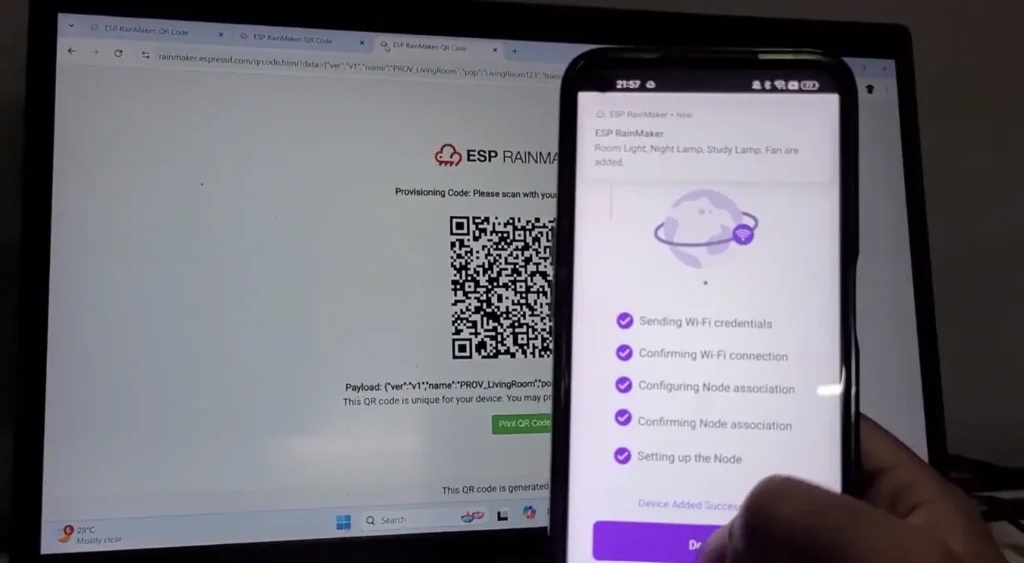
Step 4: Configure Wi-Fi
Use the ESP RainMaker BLE provisioning process to configure the network credentials. The ESP32 then attempts to connect to the configured Wi-Fi network and the ESP RainMaker cloud service.
Step 5: Control Appliances from Your Phone
Once the device is configured and online, use the ESP RainMaker app to switch the configured appliances ON or OFF. Supported voice-assistant integrations can also provide voice control.
Step 6: Use Physical Switches
The connected physical switches can control the relays directly through the ESP32. When a manual switch changes a relay state, the sketch also updates and reports the corresponding state to ESP RainMaker.
Step 7: Use Scheduling and OTA
Configure supported schedules through ESP RainMaker to automate appliances at selected times. OTA functionality allows supported firmware updates without requiring a USB cable for every update.
Step 8: Restore Stored Relay States
When EEPROM is enabled, the program saves relay states when they change and restores the saved states during initialization. If EEPROM is disabled, the sketch uses its configured default behavior instead.
PCBWay – Your One-Stop PCB Manufacturing & Assembly Solution
Have an innovative engineering project? Join PCBWay’s global design contest and showcase your creativity in Edge AI & IoT, Robotics, Power, Mechanical, or Open Theme. Win exciting prizes, including up to $2,000 in cash, PCBWay coupons, and hardware such as the NVIDIA Jetson Orin Nano Super 8GB Developer Kit.
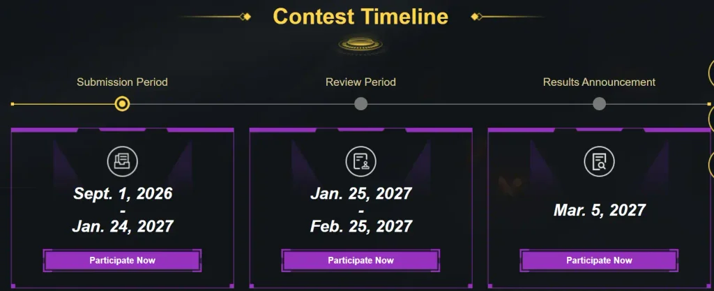
From prototype to mass production, PCBWay offers fast, reliable PCB fabrication and turnkey assembly services, supporting FR4, HDI, Rigid-Flex, RF, Aluminum, Flexible PCBs, and multilayer boards up to 24 layers.
Don’t miss these limited-time anniversary offers! Learn more: PCBWay 9th Design Contest page.
ESP RainMaker App, Google Home, and Alexa Control
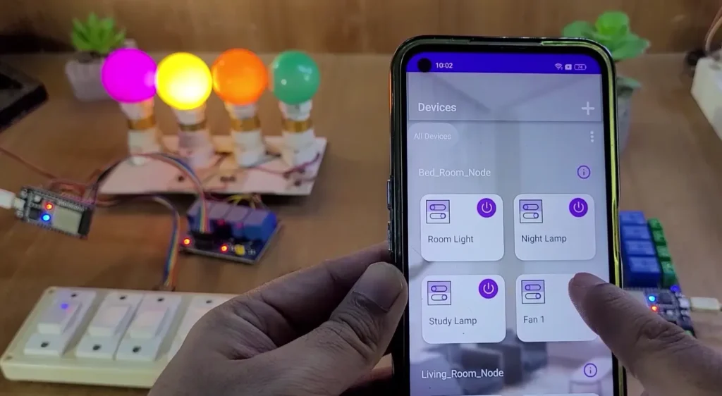
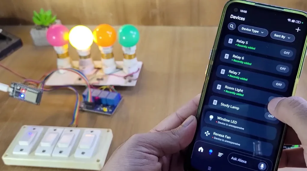
ESP RainMaker provides the cloud-connected interface for controlling the registered smart devices. Once provisioning and setup are complete, you can operate the relay devices from the mobile app when the device and cloud service are available.
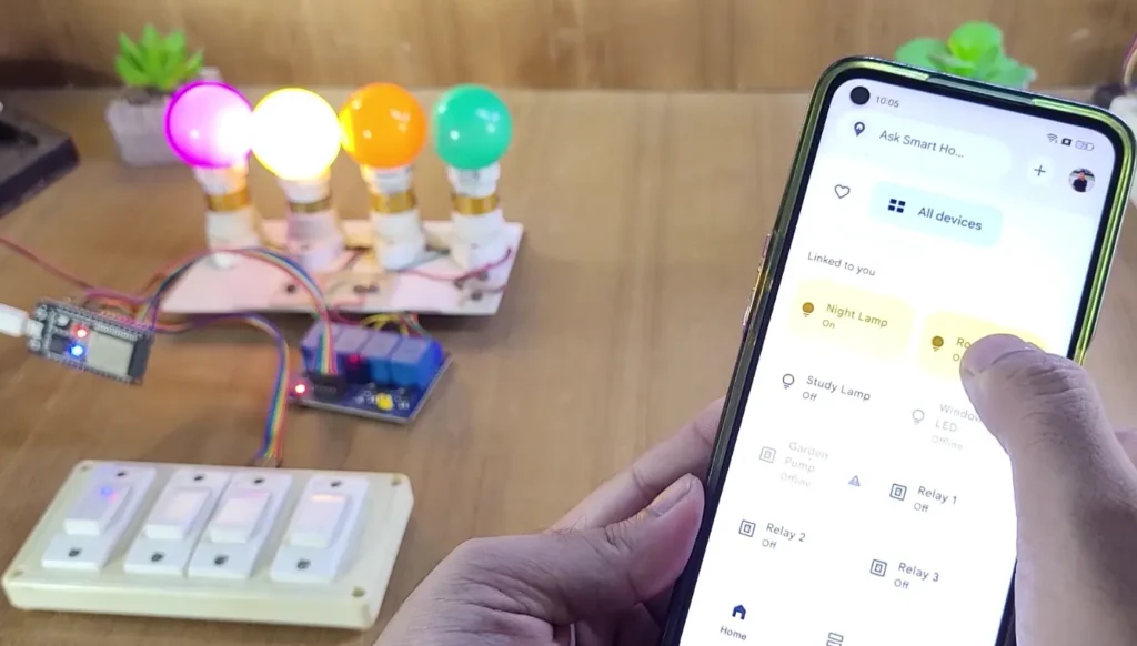
Compatible Google Home or Google Assistant and Amazon Alexa integrations can provide voice control after the relevant account linking and device discovery steps have been completed.
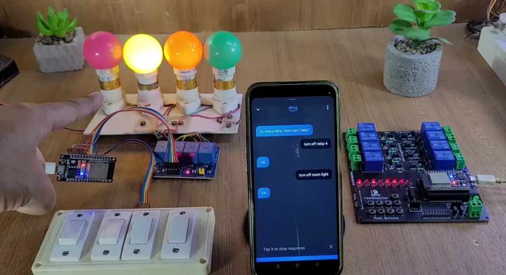
For example, you may be able to say commands such as:
- “Turn on the bedroom light.”
- “Turn off the night lamp.”
- “Turn on the fan.”
The exact commands and supported functions depend on the names assigned to the devices and the voice-assistant integration.
Manual Switch Control
A useful feature of this project is that it does not depend exclusively on smartphone control. Physical switches can operate the relays through the ESP32.
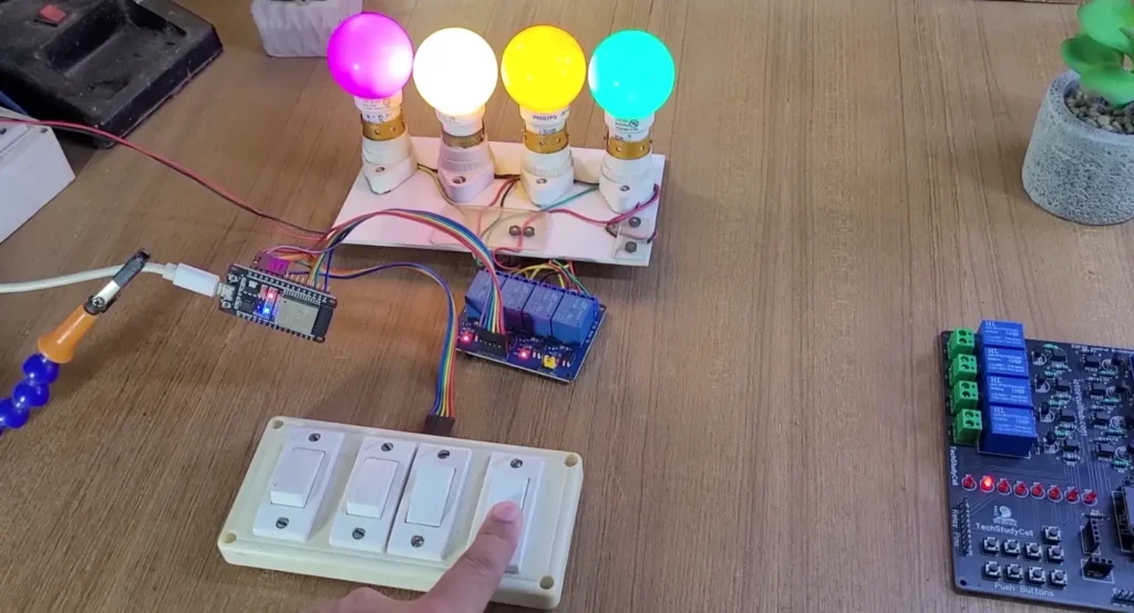
The sketch supports two configured switch modes:
- Push-button mode: A button press toggles the relay state.
- Latched-switch mode: The relay state follows the configured pressed and released events.
Choose the appropriate mode for your actual switch hardware. Test the switch behavior before connecting real appliances.
EEPROM: Saving and Restoring Relay States
The project includes an optional EEPROM-based state-storage feature. When enabled, the program records a relay’s state when it changes and can restore the saved state after a restart.
This can be useful if you want selected appliances to return to their previous software states after a power interruption.
However, the saved state is not the same as detecting the actual electrical condition of an appliance. A relay can be commanded ON while the appliance itself is faulty or disconnected. Always verify the required startup behavior for your application.
Wi-Fi Reconnection and Power Outages
If the Wi-Fi router is switched off or loses power, the ESP32 can lose its connection to the router and the ESP RainMaker cloud. The Serial Monitor may display Wi-Fi disconnection and MQTT or TLS errors while the network is unavailable.
When the router comes back online, the ESP32 must reconnect to Wi-Fi, obtain an IP address, resolve the cloud server address, and re-establish its secure MQTT connection.
In testing with the configured ESP32 Arduino Core 2.0.14 setup, the device reconnected to the router and ESP RainMaker came back online within approximately 5–15 seconds after Wi-Fi was restored. Actual recovery time can vary with router behavior, signal strength, DNS availability, and cloud connectivity.
If you are testing reconnection, turn off the router, wait at least 30 seconds, and then turn it back on. Check the Serial Monitor for Wi-Fi connection events and confirm that the RainMaker device returns online.
The code should not repeatedly restart ESP RainMaker or generate unnecessary cloud requests just to check whether Wi-Fi is available. Any additional reconnection logic should be tested carefully with the exact ESP32 core and RainMaker library version being used.
Key Advantages of This Universal ESP32 Project
- Less duplicated code: One sketch supports several relay configurations.
- Easy expansion: Increase the configured relay count when adding compatible hardware.
- Multiple control methods: Combine mobile, supported voice-assistant, and physical-switch control.
- Flexible settings: Choose the relay trigger logic, switch mode, and EEPROM option.
- Remote maintenance: Use supported OTA updates.
- Automation: Configure supported schedules using ESP RainMaker.
- Reusable framework: Adapt the project to different rooms and suitable appliances.
Limitations and Important Considerations
Although this project is flexible, there are several limitations to understand before building or installing it.
- Cloud dependency: ESP RainMaker mobile control and voice-assistant features require the relevant network and cloud services. They are not guaranteed to work when the internet is unavailable.
- Wi-Fi requirement: The ESP32 needs a compatible Wi-Fi network for the cloud-connected features.
- Voice-assistant setup: Google Home, Google Assistant, and Alexa features depend on compatibility, account linking, regional availability, and service configuration.
- GPIO limitations: Not every GPIO is suitable for every purpose. Check boot-strapping pins, board variants, connected peripherals, and the actual wiring before using the pin mapping.
- Relay compatibility: Active-LOW and active-HIGH behavior varies by relay module. Verify the trigger logic before connecting loads.
- Power supply: The ESP32 and relay module need an appropriate power supply. An inadequate supply can cause resets, unstable relays, or connectivity problems.
- State restoration: EEPROM stores the software relay state; it does not verify the physical condition of the connected appliance.
- Network recovery: Wi-Fi and cloud reconnection time can vary. Test the system after router restarts and power interruptions.
- Electrical safety: Relay contact ratings, isolation, enclosure design, and safe mains wiring are essential. This DIY project should not be treated as a certified commercial product.
Applications of ESP32 ESP RainMaker Home Automation
This universal relay controller can be adapted to a variety of DIY automation projects, including:
- Smart bedroom lighting
- Living-room light and fan control
- Night lamp automation
- Smart switches for selected appliances
- Office and laboratory automation
- Classroom lighting control
- Small-scale pump control with appropriate electrical protection
- Workshop equipment control
- Multi-room home automation prototypes
- ESP32 and IoT learning projects
Always check the electrical requirements of the appliance and use suitable switching, protection, and isolation hardware.
Frequently Asked Questions (FAQ)
Can I use the same code for 1, 2, 4, and 8-channel relay modules?
Yes. The sketch is designed to support these configurations. Change TOTAL_RELAYS, ensure the GPIO mapping matches the hardware, and upload the updated code.
Does this project work with ESP8266?
The supplied sketch is designed for ESP32 and uses ESP32-specific RainMaker and Wi-Fi provisioning APIs. It is not directly compatible with ESP8266 without substantial changes and an appropriate alternative platform.
Can I control the appliances without a smartphone?
Yes. The configured physical switches can control the relays locally. Cloud-based app and voice control require their relevant services and connectivity.
Does ESP RainMaker work without internet access?
Cloud-connected control and voice-assistant functions require network and service availability. Physical switches can still operate locally through the ESP32, provided the board and its power supply are working.
Can I update the code without connecting a USB cable?
The project enables OTA functionality through ESP RainMaker. Wireless updates depend on the correct setup, network connectivity, and compatibility of the update process.
Will the relay states be restored after a power failure?
If EEPROM is enabled, the sketch saves relay states when they change and restores them during initialization. Confirm the desired behavior for your particular appliances and installation.
Why does the device sometimes take several seconds to return online?
After Wi-Fi is restored, the ESP32 must reconnect to the router and re-establish its secure connection to the RainMaker cloud. The delay depends on the router, network, DNS, and cloud connection.
Conclusion
This ESP32 ESP RainMaker home automation project provides a reusable way to control different relay modules using a single Arduino sketch. With configurable support for 1, 2, 4, and 8 channels, manual switches, mobile control, supported voice assistants, schedules, OTA updates, and optional EEPROM state restoration, it offers a flexible starting point for DIY smart home automation. Configure the relay count, check the wiring, and test the system carefully before connecting real appliances.
If you enjoy ESP32, Arduino, IoT, and smart home automation projects, click here for more practical electronics tutorials and DIY projects.